jh6you said:Do you catch any difference in sound, MJ vs Mosfet?
JH
Slamming bass is the word!
None of both versions have more than 5mV offset.
The transistor version gives about 20W with 8ohm speakers. (Just what you need, JH)
It plays good with 4ohm also, but I didn't measure the power.
The MOS-version now has 560ohm gate resistors plus a 220 ohm. The idle current is about 170mA over the source resistors.
I increased the voltage to +/-18V.
There is more bass and high than with MJE’s. It definitely needs a volume pot; it's too loud now to listen comfortably.
Both sound very detailed, with a little preference in sound for the transistors, but increasing bias could make MOSsie sound better I guess.
4ohm is also no problem at all.
Strange thing: Nelson proposed the Mosfets to make the amp more powerful, but there is no difference.
Can someone tell me how to implement a volume pot in a balanced circuit?
Or do I put the pot in the unbalanced section?
I used Rod Elliott's balanced line driver.
/Hugo 🙂
Rookie,
You are right!... The overall gain shouldn't change, thanks!...
The reason I might need some local gain is that the LM3875 tends to oscillate at unity gain from what I have heard....
Also, if my mind doesn't fail me, once I saw a technique to 'fool' an OP amp using some sort of resistor arrangement to behave as an unity gain follower without going into instabilities, I shall dig deeper into my mind in order to rememeber...
Drakonis,
Does TI send samples to Mexico? If they do, order the OPA549. Many people have stated that it sounds better than the LM3875, and it is stable at unity gain.
Dejan
Does TI send samples to Mexico? If they do, order the OPA549. Many people have stated that it sounds better than the LM3875, and it is stable at unity gain.
Dejan
Rookie,
To be honest I don't know about it nowadays..., in the past they didn't... but things are changing a lot with this 'globalization', so I might give it a try....
Also, even when you can find locally a good deal of parts here, most DIY familiar parts must have to be ordered to US (like the OPA549)
Other interesting fact is that our local market is full of parts made by companies that happens to have plants here or some sort of 'rights', for instance, here you can find a lot of motorola, some intel, some national, some thompson, etc. parts, for others brands it is really difficult to find out a good diversity (For instance, IRF parts are kind of hard :-( when you are not a big purchaser)
Problem with Mexico is that you can not find that much DIYers that like to share thir experiences in forums like this so you can learn from them about things that can or can not happen here like the samples things....
So, I guess that I could be a pioneer in this matters here... 🙂
(in fact, if by any chance it happens to be other people from Mexico reading this I would like to know)
-MKT-
OPA549 chips
OPA549 sample chips are on backorder till mid-May I have been told today. Which bugs me. I have been waiting for them for almost two weeks and now they tell me. I guess one should not complain about free, but I would have bought them had they told me.
Between the 811's and 549's, the chip cost for each channel is almost $60.
So rookie, I will be building off your design once Digikey delivers them.
Uhhhh... lots of open questions 
* Is this a classA design ? I think no.
* I would like to make the emitter resistors smaller, about 0,22ohms or so, to have better damping.
But then the current goes up...
* The X wastes less power than the A and XA ?
* Possible to go to +/- 24V for higher Power ? I want 30 Watts.
* Does it make sense to make the idle current dependent of the input signal ? More signal, more idle current.
This is what my "madness" design does.
* Does it make sense (better sound) to run this circuit in classA ?
* Why not buid it single ended ? XA.
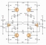
Preliminary YAX2!!! 🙂
O Yeah!!! It works!!!
Here is my working YAX2 circuit, which is a bit different from Nelson Pass original. I have R0 of 220 and R15/16 of 1.5k. These values are estimated to have maximum output current boost. Meanwhile, my pocket calculator tells me that R9-12 work well for the boosting of the output voltage swing but also work unwantedly for diminishing of the output current at the same time. Therefore, I just reserved them for the later application. I do not have any adjusting pot. Nevertheless, almost no absolute offset volt at the output nodes and almost no differential offset. I will come back with further info after listening test.
Thanks, Nelson Pass. 🙂
JH
PS. Wishing cease fire soonest...
Attachments

JH6you,
Could you send also square waves at 40 Hz and 20 Hz ?
Seems if bass are so punchy there should not be any distordance of the squares at very low frequencies.
Thanks very much.
PS.Could you do same test with sine and square at 100kHz?
Great job.Congratulations !!!
PPS Bernhard!!! Your design is threatening...chills to the bone!!!
Post 349 & 350
JH,
How many volts are you swinging on those osciligraphs ?
What load did you test with ?
BTW, that square wave looks real clean ....
Nice work JH
Dave
JH,
How many volts are you swinging on those osciligraphs ?
What load did you test with ?
BTW, that square wave looks real clean ....
Nice work JH
Dave
Looks very good, JH
Glad you finally made it!
Are you driving the amp balanced or unbalanced?
Very nice square wave, is it measured with or without load?
/Hugo 😉
Glad you finally made it!
Are you driving the amp balanced or unbalanced?
Very nice square wave, is it measured with or without load?
/Hugo 😉
You are a Pioneer!!!
Drakonis,
We are a bit far away but anyway it's good to know I found a second (that make us three) DIY's from Mexico on this forum.
We seem not to coincide on threads though but be looking to your posts and see what we can share!
🙂
drakonis said:
So, I guess that I could be a pioneer in this matters here... 🙂
(in fact, if by any chance it happens to be other people from Mexico reading this I would like to know)
-MKT-
Drakonis,
We are a bit far away but anyway it's good to know I found a second (that make us three) DIY's from Mexico on this forum.
We seem not to coincide on threads though but be looking to your posts and see what we can share!
🙂
nar said:
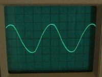
100kHz
Sign wave at 100kHz. JH
Attachments
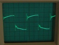
jh6you said:Square wave at 100k Hz.
JH
Ringing - singing - overshooting ?
Looks like we got a problem with the fast cfb OP.
Nelson Pass said:Bernhard, I think you've scared everybody away with that circuit.
nar said:
PPS Bernhard!!! Your design is threatening...chills to the bone!!!
Which means 😕
____________________________________________________
* Any way to make R emitter smaller ?
* Does the X-amp waste less power than the Aleph and XA ?
____________________________________________________
JH,
retry 100 ohms R9/R11 on OP output like in my design 😉
Should avoid ringing

I recognize with pleasure that you got rid of R10/R12 😀
You also can forget about R13/R14, because R3/R4 already go to virtual ground

____________________________________________________
I will try some of my ideas soon.
Bernhard said:
Ringing - singing - overshooting ?
If you are an expert, what are the ringing and overshooting?
I know the singing only.
JH

- Status
- Not open for further replies.
- Home
- Amplifiers
- Pass Labs
- Monolithic SuperSymmetry with Current Feedback