
Looks very decent to me, still we don't know which load you connected?
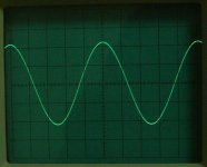
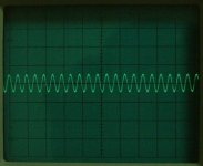
On your first sine wave 1V/div X10 you have about 9Vpp.
On the mosfet versions I have 10Vpp.
I will post some squarewaves of it later, input compared with output.
/Hugo - Wonders if this amp can be made a Class-A one?
On your first sine wave 1V/div X10 you have about 9Vpp.
On the mosfet versions I have 10Vpp.
I will post some squarewaves of it later, input compared with output.
/Hugo - Wonders if this amp can be made a Class-A one?
Netlist said:
I will post some squarewaves of it later, input compared with output.
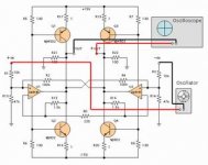
It would much appreciate if you post a brief sketch how the load, scope and oscillator are set.
Thanks.
JH
jh6you said:
It would much appreciate if you post a brief sketch how the load, scope and oscillator are set.
Thanks.
JH
Your scope and sinegenerator a correctly connected in your sketch.
The load, of course should be connected between +Out & -Out.
(Speaker 8 or 4ohm).
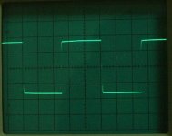
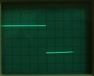
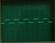
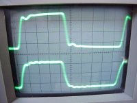
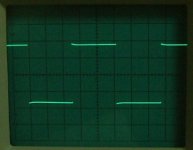
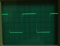
In the following pictures you'll see the input and output compared to each other.
The lowest squarewave is the input.
Input 20mV/div; Output 100mV/div. Sweep time depending on frequentie.
Here's one of 40Hz.
As you can see, my generator is rather crappie, but it's the difference between in and out who is important.
/Hugo
Attachments


jh6you, great job getting this baby to work! I am eagerly awaiting your comments on the sound.
so what happened in post #355 is completely gone by putting a few pf in the x fdbck??
Is everythink well behaved at 20-50kHz?
so what happened in post #355 is completely gone by putting a few pf in the x fdbck??
Is everythink well behaved at 20-50kHz?

grataku said:
completely gone by putting a few pf in the x fdbck??
Is everythink well behaved at 20-50kHz?
Yes, it looks so.
Yes, it looks so.
Sure will post the sound impression.
JH
If we use mosfets, on the gate resistors will drop 5V if we are lucky, which means we can use rails of 20V ( 20-5=15  ) and get more power, right
) and get more power, right Bernhard said:If we use mosfets, on the gate resistors will drop 5V if we are lucky, which means we can use rails of 20V ( 20-5=15
Bernhard,
Assuming you are talking about post #300 with, of course additional Gate resistors (220ohm)
I get the following values:
gate resistors 560ohm
Source resistors 0.47ohm
V = +/-18V
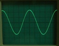
Total current dissipation before clipping: 1.8A with sinewave 400Hz
12Vpp on the scope.
Don't ask me to calculate the RMS power at 8 or 4ohm...
That's what I measured on the amp that’s currently running
I guess we might increase the voltage to 20V. Power dissipation will be 12Watt per mosfet with gate resistors of 580ohm.
/Hugo
- Status
- Not open for further replies.
- Home
- Amplifiers
- Pass Labs
- Monolithic SuperSymmetry with Current Feedback