Putting off the matter of the -5V absolute dc offset voltages for a while, I am going to play music for days. Preamp is my old tube SRPP, unbalanced. Speakers are Phase Technology PC80 (I remember it as 6 ohm 86dB).
Will post the sound impression.
JH
Will post the sound impression.
JH
Attachments
jh6you said:
The abosolute dc offset voltages are measured around -5V at all four output nodes. Hmmm...
JH
Ok, when I take out R9/10/11/12 100/220ohm (as in your drawing), my PSU's get very angry at me.
Also when removing R15/16 2.2k, I get a hell of a lot of absolute DC.
With all those R's in place I have 30mV and 35mV absolute DC which makes 5mV differential DC.
I never used R20/21
Hope this helps 😉
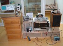
BTW, which nice CD is standing in front of that massive amp?
Nice set-up too, you cleaned up before you took the picture, didn't you?

Enjoy the music!
/Hugo
Netlist said:
R9/10/11/12 100/220ohm...
R15/16 2.2k...
I have tried all of them on and off, and others...
When I had R15/16, I had both the absolute dc and differential offset close to zero. But, problem was with the idling current as I already mentioned. For this amp, 1.3A idling current is too much, just heating up the amp without giving effect to the sound quality. I wanted the "stable" 160mA idling in order to keep the amp cool.
I get the best stable results with the latest circuit posted. With this, I could finish the amp of a good quality with a mini size of heat sink. Only concern is the absolute dc of -5V. The -5V absolute dc is nothing but might reduce the output voltage swing. Meanwhile, I would like to still believe that there must be a way to make this absolute dc lower, keeping the lower idling current. Sure, I like to find a simple method.
JH
PS. The picture is trimmed to show the clean part only. 😉
I changed the R13/14 from 47k to 300k. The aboslute dc went down from -5V to -4V. Differential offset voltages stayed at about 20mV.
I do not want to compare this amp to Zen or X-SOZV2.
My first impression is that the sound is special, tight, no vailing, detailed, enjoyable. 🙂 I am listening to Jazz, Rock and Classical music. I will see...
JH
I do not want to compare this amp to Zen or X-SOZV2.
My first impression is that the sound is special, tight, no vailing, detailed, enjoyable. 🙂 I am listening to Jazz, Rock and Classical music. I will see...
JH
Attachments

Maybe .....
JH,
Have you checked for DC offset at the input with both channels connected (as you have a DC coupled amp) ? Some strange effect in your source maybe ?
Good luck JH
dave
JH,
Have you checked for DC offset at the input with both channels connected (as you have a DC coupled amp) ? Some strange effect in your source maybe ?
Good luck JH
dave
JH,
is there something special with MJ802-4502? Could they be sub with something more up to date/better sounding? Like Sankens?
is there something special with MJ802-4502? Could they be sub with something more up to date/better sounding? Like Sankens?
Netlist said:
8ohm: 16Vrms * 1.5Arms = 24Wrms
4ohm: 10.5Vrms x 1.85Arms = 19.4Wrms
Got the feeling there could be something wrong here...

Ha, ha, ha ! This is the joke about this amp.
The amp makes current flow.
And a higher impedance with same current gives higher voltage --> gives more watt

Bernhard said:
Ha, ha, ha ! This is the joke about this amp.
The amp makes current flow.
And a higher impedance with same current gives higher voltage --> gives more watt
Without a practical example I can't understand what you mean
about that current and voltage trick. 😕
Are these values normal or not?
Enlighten me.
And how is your progress?
/Hugo - is a practical man.
Netlist said:
Without a practical example I can't understand what you mean
about that current and voltage trick. 😕
Are these values normal or not?
Enlighten me.
And how is your progress?
/Hugo - is a practical man.
When we look at the bipolar version with NPN/PNP we have a quiescent current through the OPs.
This gives us a voltage over the base bias resistor.
This voltage minus 0,65V gives the voltage on the emitter resistor.
This voltage / ohms of the resistor gives us the emitter-collector current.
Because both the emitter resistor and the voltage across the emitter resistor are fixed, also the current is fixed, so this is a constant current source.
If we apply a voltage on the + amp input and the same but negative voltage on the - amp input, we increase the current through the upper left and the lower right bias base resistor.
This gives us a higher voltage over the both base bias resistors.
This gives also a higher voltage on both the emitter resistors.
This higher voltage on the resistors gives us higher emitter-collector currents.
Lets say, we have 250mA idle current through both sides, 0mV offset voltage

Now the upper left and lower right current is 500mA, the others remain 250mA.
We have 4 constant current sources now, 2 x 250mA and 2 x 500mA.
Because lower left and upper right are willing to sink / source only 250mA, but the other two want sink / source 500mA, the current splits through the load.
And 250mA will flow through the load from left to right, no matter if this is 4 ohm or 8 ohm.
250mA x 4 ohm = 1V 250mA x 8 ohm = 2V
250mA x 1V = 0,25W 250mA x 2V = 0,5W
I mentioned that already in one of my very early posts.
the amp input signal modulates the current of the current sources, by modulating the current through the base bias resistors.

This is a MCSA modulated current sources amplifier
No further progress so far, my amp works for a long time anyway, I just can't decide about bipolar or mosfet and TO3 mos or TO247 mos.
Also as you know I try to figure out about issues like dynamic idle current, see my madness circuit...
And I'm not shure which transformer voltage and power and if stabilized or not and what is the best idle current and, and... 😕
Very nice and clear explanation, I will print it and hang it on the wall in front of me and read it again and again until I (maybe) one day will understand the mystery of transistors and electronics.
As I said, I'm a practical man and theory is extremely difficult to me and sometimes very frustrating not to understand it...
That's why I can't comment your "madness" 😉
Maybe one day.
Thanks
/Hugo
As I said, I'm a practical man and theory is extremely difficult to me and sometimes very frustrating not to understand it...
That's why I can't comment your "madness" 😉
Maybe one day.
Thanks
/Hugo
Re: Maybe .....
I have checked the DC offset with no input-output connection at all, with all connections, and during playing music. In any case, the DC has been maintained at -4V with few tolerances (drifts).
JH
DRC said:
DC offset
I have checked the DC offset with no input-output connection at all, with all connections, and during playing music. In any case, the DC has been maintained at -4V with few tolerances (drifts).
JH
Nelson Pass said:
Most likely you are suffering from a lack of open loop gain.
Try a lower value of R0.
I have not touched R0 yet. Will see lower values. Thanks.
JH
grataku said:
Could they be sub with something more up to date/better sounding?
I believe so.
I am trying to complete a cute and sexy sub system. 😉
JH
Hmmmmm. i have no real need for another amp at the moment, but this has inspired me to try a similar design for a preamp using mat02-03.
Good work guys!
I bet it sounds great.
Good work guys!
I bet it sounds great.
Re: Re: Maybe .....
Why not try my version ? The one you believe its got not much power, works fine without DC offset
jh6you said:
I have checked the DC offset with no input-output connection at all, with all connections, and during playing music. In any case, the DC has been maintained at -4V with few tolerances (drifts).
JH
Why not try my version ? The one you believe its got not much power, works fine without DC offset
Seems that I 've figured out how to build that amp with N-fets only.
IRFP240, IRFP064 and friends.
IRFP240, IRFP064 and friends.
Re: Re: Re: Maybe .....
JH,
Please note that the only reference to ground in this circuit comes from through R13 and R14. If one of the output drifts upwards, say the +output for example, there will be current through R2, which will flow through R13 and move up the + input. U1 really cannot do anything about this; it can move the -out terminal up (and will do that) which justs means you get the same situation on the -output and U2. So, in the end, both are sitting happily at the same level, but it has no reference to ground. The fact that it floats upward probably has to do with the relative beta of the PNPs versus the NPNs. I predict that if you change R13 and 14 to say 10K the offset gets to around 1V, increasing your dynamic range. Alternatively (or at the same time) you can increase R2 & R4, but that will increase the differential offset and/or the noise level. But it may help.
Also note that in this situation there is no current through R0 (both terminals at the same level) so its value is to a large extend immaterial (there will be SOME current resulting from the circuit imbalances).
Anyway, the above are bandaids, something basically is missing in this amp, I just don't know what it needs yet.
Jan Didden
jh6you said:
I have checked the DC offset with no input-output connection at all, with all connections, and during playing music. In any case, the DC has been maintained at -4V with few tolerances (drifts).
JH
JH,
Please note that the only reference to ground in this circuit comes from through R13 and R14. If one of the output drifts upwards, say the +output for example, there will be current through R2, which will flow through R13 and move up the + input. U1 really cannot do anything about this; it can move the -out terminal up (and will do that) which justs means you get the same situation on the -output and U2. So, in the end, both are sitting happily at the same level, but it has no reference to ground. The fact that it floats upward probably has to do with the relative beta of the PNPs versus the NPNs. I predict that if you change R13 and 14 to say 10K the offset gets to around 1V, increasing your dynamic range. Alternatively (or at the same time) you can increase R2 & R4, but that will increase the differential offset and/or the noise level. But it may help.
Also note that in this situation there is no current through R0 (both terminals at the same level) so its value is to a large extend immaterial (there will be SOME current resulting from the circuit imbalances).
Anyway, the above are bandaids, something basically is missing in this amp, I just don't know what it needs yet.
Jan Didden
Bernhard, Those IRFPxxx are the official Pass amp devices.
Definately a good idea!
We all have a few of 'em laying around, so I agree, that should get some interest going for your scheme!
Definately a good idea!
We all have a few of 'em laying around, so I agree, that should get some interest going for your scheme!
- Status
- Not open for further replies.
- Home
- Amplifiers
- Pass Labs
- Monolithic SuperSymmetry with Current Feedback