One day I will build a +/- temp controlled DAC/preamp box just for the heck of it....this could be the ultimate tweak 😉.higher mobility..ie..faster the devices.and also.less noisy...🙂
Dan.
Member
Joined 2006
Dont go crazy like you on pepsi please 😀.
It should not be noticable in the range of temp you likely can do.. 😉
It should not be noticable in the range of temp you likely can do.. 😉
Member
Joined 2006
lower mobility and lower noise as temp goes down.
Not quite....I know this stuff well..and have a record on one...see my bios😎
I actually wanted to lower the gain of the MOD86. A gain of 1 V/V (straight wire, no gain 🙂) would be nice. I was not able to make the compensation work for that without sacrificing loop gain at 20 kHz, hence, performance. I've decided to live with a gain of 10 V/V (20 dB).
As others have pointed out, you can lower the total gain of the MOD86 or PAR86 by swapping the THAT1200 for a THAT1206.
Tom
What about introducing a voltage dividier between the THAT and LME? The THAT may drive resistive loads down to 2k-Ohms. One can easily lower the overall gain to 0dB this way, but there are several drawbacks:
- A horrible gain structure
- need to cut a pcb trace
- Lower load impedance may degrade THAT performance
- Higher source impedance seen by the LME may degrade its performance
- additional noise introduced by the divider resistors
- you need to find the right spot to connect the GND-End of the voltage divider to to avoid coupling in unwanted signals through it.
any thoughts?
Ben
What changes with temp...
Everything. Seriously!
White noise, 1/f noise ?.
Those questions can be answered by looking at the mechanisms that cause the noise.
Thermal noise (white), as the name indicates depends on temperature. Temp goes down, noise goes down. Thermal noise is caused by the random movement of carriers.
Shot noise (also white) is caused by the flow of carriers. It's proportional to current and not temperature dependent.
1/f noise is caused by carriers getting stuck in traps caused by impurities in the semiconductor manufacturing process. The carriers stay in the traps for an amount of time. This amount of time is random but with a preference towards the longer end. When the carrier snaps out of the trap, it creates a pop. So you'll have a noise component that's frequency dependent. To my knowledge, this is not (significantly) dependent on temperature.
What happens when approaching and then going lower than -60C ?.
Integrated circuits these days are usually designed for -40 to +85 C operation. There are some applications that want to extend the operation at either end. Automotive requires operating up to +125 C and higher if it's a component that goes on the engine. Military and space tend to want to push the low end.
I have served a few customer requests at my day job, where the customer wanted to buy a -40 C rated part but wanted to know what would happen at -50 C or -60 C as they did some testing at those temperatuers to ensure that their equipment could start up when mounted outside in Siberia. I seem to recall that the ICs worked at those temperatures. The performance won't be guaranteed, but the ICs did work.
Tom
semiconductors don't all work well in liquid nitrogen.
I believe many start to give up their useful properties at around -60°C
Tell that to the people who operate GaAs LNAs cooled by liquid helium. Helium, by the way, boils at 4 K (-269 ºC). Helium cooled circuits can usually get down around 25 K as they're limited by the thermal conduction to the outside world.
Tom
What about introducing a voltage dividier between the THAT and LME?
Then you might as well just turn the volume down at the preamp. It would have the same impact on the gain structure.
Using the THAT1206, the MOD86 gain becomes 14 dB (5 V/V). With a 2 V RMS input signal, that'll result in 7-8 W by the time the dropout across the LM3886 is taken into account. I'm not sure I'd go much lower on the gain on that one.
For pico-power no-gain power amps, there are a few more options. One could put some LME49600s in parallel, for example. Just watch the thermals....
Tom
Actually, preferred circuit topology varies as a function of gain. Optimizing for unity also favours different part selection in everything from resistors to ICs. I hope to have a composite amplifier board for gains of 0 to 6dB available in roughly the end of this year to early 2016 timeframe. Using best available parts to get best available performance means it'll be a medium pitch surface mount design, likely with a few 0805 or 1206 four terminal components to solder. 1A or 2A peak output current and some tradeoff of CMRR compared to the Mod to better balance the design for good performance across other measurements. Maths suggest it should it hit -123dB THD+N. But I'll have no proper way of verifying that as there isn't really measurement gear which can go that low.Do I need to alter compensations with these lower gains?, which module at which freq? ...
Relatively high wattage, through hole builds are popular in the DIYer market. So lower power, surf mount amps would seem to be something of a niche application, maybe running to bi/tri/quadamp arrangements. As such it's not at all clear there's a business case to approach someone like Tom with to explain why it'd be worth his while to offer the boards. If the interest is there I'll try to make it happen, though.
I'm sorry I even brought up the LN2 thing for low-noise electronics...hahaha. It's been a few years (so CFT will have to correct me if I'm wrong) but that exp(-kt/q) term pops up all over the place, and heavily drives recombination and shallow traps.
Member
Joined 2006
Hahaha..its been years for me as well...🙂
I thought someone sooner would also mention high temperature superconductors...😀
Indeed.....at very low temp things will calm down and provide a darker environment...yet with more agile actions taking place..like the kT you showed.
I think LN2 is at a right temp..LHe is a bit of an overshoot and really expensive too to operate...(I used a lot then for pumping it down to superfluid @1.8K or -271C for measurement purposes) ..ok...ok..way OT..😱
BTW, all these microscopic phenomena already absorbed in the chip data...so luckily no need to really understand it for making a nice amp like Tom's.🙂
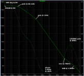
I printed the figure attached to post #1359 above, and drew some asymptotes on the graph. They indicate
Have a look at the phase of the transfer function in the treble region around 1 kilohertz. Cowabunga!
(Tom only showed the magnitude plot {green solid line} and not the phase plot {green dotted line} so I suppose there's a chance that my simple model got the magnitude right but the phase wrong; although I doubt it}
BEWARE: this is a big image file and you'll lose resolution unless you view it at full screen magnification.
- pole at 0.06 Hz ... transition from 0 dB/decade to -20 dB/decade
- pole at 13 Hz ... transition from -20dB/decade to -40 dB/decade
- zero at 78 kHz ... transition from -40dB/decade to -20 dB/decade
- pole at 3 MHz ... as shown on the LM3886 datasheet
Have a look at the phase of the transfer function in the treble region around 1 kilohertz. Cowabunga!
(Tom only showed the magnitude plot {green solid line} and not the phase plot {green dotted line} so I suppose there's a chance that my simple model got the magnitude right but the phase wrong; although I doubt it}
BEWARE: this is a big image file and you'll lose resolution unless you view it at full screen magnification.
Attachments
not too big:
size: 57.61 kB (58,991 bytes)
dimensions: 1,053px × 968px
actually quite small and still easily legible.
Just goes to show why we don't need 5Mega pixel and bigger that some post here and some that use remote servers that automatically download near 1Mb files without us asking to see the big pic.
size: 57.61 kB (58,991 bytes)
dimensions: 1,053px × 968px
actually quite small and still easily legible.
Just goes to show why we don't need 5Mega pixel and bigger that some post here and some that use remote servers that automatically download near 1Mb files without us asking to see the big pic.
Does the 1.5degrees @ 1kHz matter?
What if the actual margin moved a little during operation?
What if it became -0.5degrees while shutting down, or starting up, or during a high power period when supply rails are low, or etc...?
What if the actual margin moved a little during operation?
What if it became -0.5degrees while shutting down, or starting up, or during a high power period when supply rails are low, or etc...?
No.Does the 1.5degrees @ 1kHz matter?
This is called conditional stability in da old text books when it was relevant to valve amps starting up.
Almost completely irrelevant today with SS except for really poor designs.
The true criteria for stability isn't if the phase goes 180. It's whether Bode's Return Ratio encircles (-1,0). LTspice has a Nyquist Plot that allows you to investigate this.
So if the phase at 1kHz is 178.5degrees it is OK. I think we are all agreed.
If it changes to 179degrees, is it still OK?
If it changes to 179.5degreees, is it still OK?
If it changes to 179.9degrees, is it still OK?
How close can that dip get to 180degrees and that we can guarantee that it never exceeds 179.9degrees?
There must be tolerances in component values and device parameters.
There must be variations in loading reactances. Even the output Zobel components will have tolerances.
Mark wrote:
almost no one posts simulation predictions using this format
If it changes to 179degrees, is it still OK?
If it changes to 179.5degreees, is it still OK?
If it changes to 179.9degrees, is it still OK?
How close can that dip get to 180degrees and that we can guarantee that it never exceeds 179.9degrees?
There must be tolerances in component values and device parameters.
There must be variations in loading reactances. Even the output Zobel components will have tolerances.
Mark wrote:
He is concerned about how close his simulation gets to 180degrees and Mark knows a lot more than me.Have a look at the phase of the transfer function in the treble region around 1 kilohertz. Cowabunga!
almost no one posts simulation predictions using this format
It's whether Bode's Return Ratio encircles (-1,0). LTspice has a Nyquist Plot that allows you to investigate this.
Too many pages too read. Can someone tell me where's the schematic for this project first of all?
you only have to look at post 1 of the thread. Or go here Modulus-86 Rev. 2.0: Composite amplifier achieving 0.000067 % THD.
I would normally direct you to post1.
But this seller is keeping much in secret (to protect his I.P.) and will maybe release full information after you commit to buying the quite expensive PCBs.
But this seller is keeping much in secret (to protect his I.P.) and will maybe release full information after you commit to buying the quite expensive PCBs.
where's the schematic for this project
I can't see the schematic in post1 nor in the link you have provided.you only have to look at post 1 of the thread. Or go here Modulus-86 Rev. 2.0: Composite amplifier achieving 0.000067 % THD.
- Home
- Vendor's Bazaar
- Modulus-86: Composite amplifier achieving <0.0004 % THD+N.