Actually Zobels are most useful when they are as close to the Output Devices as possible.
Yep. The Zobel needs to be at the output stage. Must ... minimize ... inductance.
Some speakers will have an RC network across the terminals to tame the speaker impedance. That is a completely different animal with its own issues.
Tom
the OUTPUT Zobel must be fitted at the output devices and must have a low loop impedance to allow the high frequency loading effect to actually work.
This is repeated all over this Forum and is in the various papers published by our experts.
The next part is the remainder of the Thiele Network, the L||R.
This should be fitted somewhere in the route from amplifier to speaker terminals (on the amplifier).
Then there is the other (R+C) as described by Neville Thiele. This must be after the L||R.
Alternatively the last R+C can be an additional network that the amp is not using as a stability enhancing component but as an RF filter to attenuate speaker cable interference signals before they get inside the amplifier feeding the -IN pin at the input of the amp.
If this last is added then one ends up with a Pi filter. Zobel (R+C) at the output device, L||R in the route to terminals and Zobel at the speaker terminals.
Yup, that's what I meant.Some speakers will have an RC network across the terminals to tame the speaker impedance. That is a completely different animal with its own issues.
Tom
Agreed, amplifier zobel is different deal, my bad.
Dan.
the OUTPUT Zobel must be fitted at the output devices and must have a low loop impedance to allow the high frequency loading effect to actually work.
Agreed.
The next part is the remainder of the Thiele Network, the L||R.
This should be fitted somewhere in the route from amplifier to speaker terminals (on the amplifier).
The Thiele network (L||R) decouples the load capacitance (think speaker cable capacitance and electrostatic speakers) from the amp at frequencies well above the audio band (>100 kHz). To work effectively, it needs to be mounted reasonably close to the output stage. I put the Thiele network on the amp PCB. Some prefer to put them at the amp output terminals. Either approach is valid, assuming the connections from the amp output to the Thiele network are reasonably low capacitance connections (< 1 nF).
Then there is the other (R+C) as described by Neville Thiele. This must be after the L||R.
Last I checked, I didn't see any impact on amp stability of the second Zobel (R+C) network. I'll be more than happy to take another look when time allows, though. The stability section of my Taming the LM3886 page could use an update anyway.
Tom
If the first R+C is omitted and the C is placed across the speaker terminals after the L||R, then at high frequency the amplifier sees the R and the C as it's load, This works like a Zobel, but attached via the internal speaker cables.Last I checked, I didn't see any impact on amp stability of the second Zobel (R+C) network. I'll be more than happy to take another look when time allows, though. The stability section of my Taming the LM3886 page could use an update anyway.
The "remote" Zobel is affected by the intervening cable. I suspect that the cable effect reduces the effectiveness of this second form of the Thiele Network. See below.
The Network described by Neville Thiele was a combination of R+C and L||R.
It came in two forms.
R+C at the output followed by L||R feeding the load.
or
L||R feeding the load followed by C across the load.
Dr Cherry did an analysis of these two forms and showed that they are at the extremes of a continuum with infinite variety of values between the two limiting forms given by Thiele.
However, once the first form is adopted, the L||R, at least partially, isolates the second Zobel from the amp output.
The second Zobel, as a result, has virtually no stabilising effect on the amplifier.
But it does have an RF attenuating effect. Cherry and others mention this.
I have adopted this Pi version (two Zobels and an Inductor) since it seems to do three important jobs (it is three groups of components)
a.) first Zobel provides an HF load to help stabilise the amplifier gain.
b.) the inductor with, or without, the damping resistor helps isolate reactive loads from affecting the feedback of global feedback amplifiers.
c.) The second Zobel attenuates RF from the speaker cables to help reduce injection of HF into the -IN pin of the amplifier.
To perform each of these functions:
a. must be at the amp output.
c. must be at the speaker terminals.
b. The flux from the inductor should be kept away from the sensitive parts of the amplifier and away from steel panels.
Do aluminium panels have an effect on the inductor. Eddy currents flow in aluminium.
Last edited:
I have always used zobels as a way to creat a near resistive load to the amplifier, works quite well, but the zobel for the amp output adds that extra smoothness to the sound.
Sent from my iPhone using Tapatalk
Sent from my iPhone using Tapatalk
I've overlaid the open loop frequency response of a standard discrete-transistor power amplifier, from Bob Cordell's book p.174. It's in yellow; the modulus-86 is in green. Yellow is NOT a chip-amp, it's a dozen discrete transistors and some passive components, on a printed circuit board; Cordell's book goes into great detail.
Also attached is a distortion-vs-frequency plot of the LM3886 chip all by itself (i.e. not in a compound amplifier). Its weak zone is from 500Hz to 20kHz; in this region the Modulus-86 provides an extra ~30dB to ~0dB of gain for additional distortion reduction.
_
In all fairness, I think you are comparing apples to oranges - so to speak. 🙂
The Modulus 86 has two pole compensation type phase / OLG characteristics
and would be better compared to a similar discrete power amp design more
along the lines of Edmund Stuarts designs. These amps, from memory
acheived an actual measured distortion of -120dB at 200Watts / 4 ohms
20kHz. Below 20kHz - pretty irrelevant it just goes down even further.
If have a discrete, high OLG two pole compensated amp that I designed built
myself. From memory, in Ltspice the OLG was at least 120dB at lower
frequencies. It also simulated very low distortion into 4R / 20kHz / 200W
and at frequencies of 1kHz virtually none but unfortunately I don't have
anything to measure such distortion levels.
The important point to take home here though is that in extensive listening
tests, the compensation has quite an effect on sonic performance. I'm not
convinced yet that throwing away phase margin for OLG early in the FR is
the magic bullet for a great sounding amp. More work to be done in this
area.
Tom, how many of these Modulus amps are out there and are there any real
listening evaluations using a great system in stereo?
The in depth tech talk here is certainly interesting but I'd like to see more
subjective evaluation, obviously put in the right perspective.
We all know the importance of great measurements but I believe subjective
evaluation is just as important.
cheers
T
There are many aspects related with good sound reproduction. Generally you want to try to address all of them while finding a right balance. I do not think anyone has done this systematically to change the balance of each aspect and find out what kind of design balance works best. But you are also going to be effected by the speaker driver eventually, so optimally, the amp can only be designed to best perform with specific driver parameters, characteristics, and design.
Sent from my iPhone using Tapatalk
Sent from my iPhone using Tapatalk
I read many pages in this thread, but only read less than 5 user reviews. Surely there must be more people who have built this amp and had something good/bad/neutral to say about it? Hmm
You can get very different opinions depending on system setup and personal preference. Quite confusing if the description is not to sufficient detail. I wished to see a few other measurements, but I guess it is not going to happen. Currently I have not time to focus my kit since it missed the window of opportunity. Will just have to slip in some work on it here and there.
Sent from my iPhone using Tapatalk
Sent from my iPhone using Tapatalk
Sure, I understand that. I was more curious about relative comparisons to other amps that the builders were already using.
Tom, how many of these Modulus amps are out there and are there any real
listening evaluations using a great system in stereo?
I read many pages in this thread, but only read less than 5 user reviews. Surely there must be more people who have built this amp and had something good/bad/neutral to say about it? Hmm
The builders who have provided feedback to me have all been overwhelmingly impressed by the amp. I've included a few testimonials on my Modulus-86 page.
You may find a few more reviews in the Modulus-86 Build Thread: http://www.diyaudio.com/forums/chip-amps/267802-modulus-86-build-thread.html
I've sold well over 100 Modulus-86 boards now. I don't know how many of them have been built yet. I suspect the builders who have completed the amp are busy enjoying the music rather than clacking away at their keyboards writing up reviews. 😉
Tom
I suggested installing full CRC snubbers into the Power86 back in December 2014 (post#408) but tomchr decided against it. The design and PCB layout of Power86, pictured on the sales website, is simple and straightforward, so I was dismayed (post #539) by its rather high sales price: USD 50.00. I pointed out that hobbyists could lay out their own Power86-like PSU boards and get TEN boards of their design fabbed, for less money.
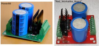
So ... that's what I did. In Phase 1, I designed and layed out and sent to fab, a Power86 PCB work-alike board. Same simple cicuitry, same components, same full-ground-plane layout, same big honking topside copper "pours" for VPOS and VNEG. It's shown in Figure 1 below.
At left is the photo from the Power86 website; on the right is my work-alike board (red laminate). When the components are stuffed and soldered, the result is Figure 2. You can see that the Workalike board uses the same connectors, same bridge rectifier with same Aavid heatsink, and the same Cornell Dubilier capacitors.
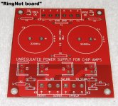
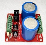
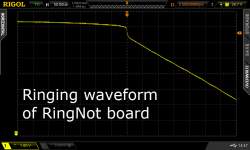
Then, in Phase 2, I upgraded the circuit design. I added 30 Ampere Soft Recovery Diodes, and full CRC snubbers for each secondary. These completely eliminate any and all oscillatory ringing in the transformer secondary. The Phase 2 board design, called RingNot, is shown in Figures 3 and 4 below.
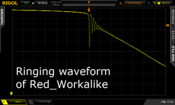
As expected, the RingNot board has completely eliminated all oscillatory ringing in the transformer secondary (Figure 6). The Power86/Workalike board (Figure 5) does not perform nearly as well. Why live with this kind of unwanted ultrasonic ringing junk when you don't have to?
I'm giving away the Phase 2 design and the layout and the Builder's Guide and the PCB Manufacturing "Gerber Files", for free. Just search diyAudio for RingNot, you'll find them. Send the Gerbers off to a PCB fab and away you go! I provide three full BOMs for the three most popular distributors.
I built quite a number of these boards myself, sourcing parts from DigiKey. I've got some leftover bare boards that I'm getting rid of, at my cost ($15 to $6 depending on payment method). I've also got some fully populated, soldered, assembled + tested, finished power supplies that I'm also selling at my cost ($50 to $33 depending on payment method). Search diyAudio for RingNot to see the whole shebang.
Tomchr still sells the bare Power86 PCB for $50.00. But now you've got additional options. Bare RingNot PCB for $15.00. OR complete RingNot supply, assembled and tested, for $50.00. OR send the Gerbers off to fab and get ten RingNot bare boards for about $40; use one and give away or sell the others. It's pleasant to have options.
_
So ... that's what I did. In Phase 1, I designed and layed out and sent to fab, a Power86 PCB work-alike board. Same simple cicuitry, same components, same full-ground-plane layout, same big honking topside copper "pours" for VPOS and VNEG. It's shown in Figure 1 below.
At left is the photo from the Power86 website; on the right is my work-alike board (red laminate). When the components are stuffed and soldered, the result is Figure 2. You can see that the Workalike board uses the same connectors, same bridge rectifier with same Aavid heatsink, and the same Cornell Dubilier capacitors.
Then, in Phase 2, I upgraded the circuit design. I added 30 Ampere Soft Recovery Diodes, and full CRC snubbers for each secondary. These completely eliminate any and all oscillatory ringing in the transformer secondary. The Phase 2 board design, called RingNot, is shown in Figures 3 and 4 below.
As expected, the RingNot board has completely eliminated all oscillatory ringing in the transformer secondary (Figure 6). The Power86/Workalike board (Figure 5) does not perform nearly as well. Why live with this kind of unwanted ultrasonic ringing junk when you don't have to?
I'm giving away the Phase 2 design and the layout and the Builder's Guide and the PCB Manufacturing "Gerber Files", for free. Just search diyAudio for RingNot, you'll find them. Send the Gerbers off to a PCB fab and away you go! I provide three full BOMs for the three most popular distributors.
I built quite a number of these boards myself, sourcing parts from DigiKey. I've got some leftover bare boards that I'm getting rid of, at my cost ($15 to $6 depending on payment method). I've also got some fully populated, soldered, assembled + tested, finished power supplies that I'm also selling at my cost ($50 to $33 depending on payment method). Search diyAudio for RingNot to see the whole shebang.
Tomchr still sells the bare Power86 PCB for $50.00. But now you've got additional options. Bare RingNot PCB for $15.00. OR complete RingNot supply, assembled and tested, for $50.00. OR send the Gerbers off to fab and get ten RingNot bare boards for about $40; use one and give away or sell the others. It's pleasant to have options.
_
Attachments

I don't think I understand the measurements, what are the flat and sloping parts? What are the horizontal and vertical axis?
Sent from my iPhone using Tapatalk
Sent from my iPhone using Tapatalk
Should be the voltages on one of the secondaries as the diodes close under some load---the not quite flat beforehand is the charging sustain from the mains peak and the slope the discharge out of the caps. Tom's already demonstrated lack of feedthrough to the amp output so this is kind of OT; an amp would need to have lower PSRR than the Mod for the snubbing to offer subjective benefit.
I recall the dead horse about lack of difference between CRC and RC snubbing being more than adequately flogged earlier in this thread too.
I recall the dead horse about lack of difference between CRC and RC snubbing being more than adequately flogged earlier in this thread too.
The Modulus-86 and Parallel-86 have been extensively characterized using the Power-86 circuit. The results can be found in this thread (see links in Post #1) as well as on my website - Neurochrome Audio: Precision high performance audio circuits for the DIY market..
I have yet to measure or hear any effect of supply snubbing on the MOD86/PAR86 circuits.
Tom
I have yet to measure or hear any effect of supply snubbing on the MOD86/PAR86 circuits.
Tom
There are lots of issues at -20~-60 snow range in most systems, it would take skill to identify all other issues until these are taken care of. Most are in the category of delayed release of stored energy and interaction between equipment...
Sent from my iPhone using Tapatalk
Sent from my iPhone using Tapatalk
@Mark: Pleased you are contributing to the DIY effort, but I have to ask why you have chosen to do a marxist attack on someone in the vendors forum. If you don't like someones pricing structures fine, but make your own thread so more people can see this board and buy it, or maybe offer it to the DIYaudio store. Posting here just seems like you have a chip on your shoulder.
Is not entrepreneurial competition as capitalistic as it gets, to set price based on performance/service in a competitive market as opposed to monopoly?
If the price difference between fabbed PCB & store price is mostly engineering, it's hard to justify 50$ for a pretty straight forward unregulated PS. The amplifier on the other hand is a different animal.
Guess it's up to Tom if he wants to sacrifice valuable time (which he might not have) to take measurements and compare. If there is no measurable difference it would be yet another verification of the amplifiers excellent PS immunity.
Hopefully this potential can-o-worms will lead to interesting test results and possible improvement instead of fussing & fighting.
- Home
- Vendor's Bazaar
- Modulus-86: Composite amplifier achieving <0.0004 % THD+N.