For a chip amp, the last stage has about 20x~45x gain not counting any input buffering which may contain gain or attenuation...That doesn't really change my confusion, as this still means lower loop gain which leads to higher output impedance.
The "amplifier gain" as you define it will be a little less than 0dB in most designs, as the last stage often is a voltage follower.
Raising SNR:
The linear regulators on the MOD86 need to drop quite some voltage as they are fed directly from the HV rail (How much depends on the transformer secondary voltage of course). Is there some headroom in respect to power handling / thermal design if i wanted to use the MOD86's +-15V rails for additional circuitry?
Ben
For a chip amp, the last stage has about 20x~45x gain not counting any input buffering which may contain gain or attenuation...
Here's the LM3886 Datasheet:
http://www.ti.com/lit/ds/symlink/lm3886.pdf
go to page 7 and please tell me where this quasi complementary darlington output stage has gain.

Ben
Note that the Mod-86 is a composite. There is 150dB of open loop gain and that output stage is in the feedback loop. You have to bear this in mind. For normal chip amp discussions there are other threads....
Flex, Soon is referring to the chipamp as the last stage in a music system.
The usual chipamp gain as he has stated is around 20x to 45x
This must be adjusted by the preceding gain/attenuation of the pre-amp.
The usual chipamp gain as he has stated is around 20x to 45x
This must be adjusted by the preceding gain/attenuation of the pre-amp.
Note that the Mod-86 is a composite. There is 150dB of open loop gain and that output stage is in the feedback loop.
Yep. The LM3886 sees an additional 95 dB of loop gain due to its local loop, so the total loop gain applied to error-correct the LM3886 is approaching 250 dB.
Flex, Soon is referring to the chipamp as the last stage in a music system.
The usual chipamp gain as he has stated is around 20x to 45x
This must be adjusted by the preceding gain/attenuation of the pre-amp.
I'm not sure how this relates to the MOD86 or PAR86, though. Composite amplifiers provide much, much better performance than a regular chipamp due to the much higher loop gain.
Tom
Post1341 made a statement.....................I'm not sure how this relates to the MOD86 or PAR86, though. Composite amplifiers provide much, much better performance than a regular chipamp due to the much higher loop gain.
Tom
Post1342 said that statement was wrong.
I interjected to hopefully clarify the misunderstanding.
at what range of frequencies?......................the total loop gain applied to error-correct the LM3886 is approaching 250 dB............
DC to 1Hz ?
or 0.1Hz to 1kHz?
or at 20kHz?
Andrew, it is quite easy to calculate for yourself. Specsheets are freely available on the interwebs. Just multiply the open loop gain at the frequency of interest of both devices. For example, this would give you 120 dB @ 20KHz. Divide this gain by the closed loop gain and you know how much is available for error correction.
Last edited:
If the feedback is single pole, then it is indeed fairly easy to model the open loop gain response.
But I doubt this composite is a single pole roll-off.
BTW, "fairly easy" starts by identifying the zero dB gain crossover frequency and working back via the 6dB/octave or 20dB/decade.
Do we know the gain crossover frequency?
But I doubt this composite is a single pole roll-off.
BTW, "fairly easy" starts by identifying the zero dB gain crossover frequency and working back via the 6dB/octave or 20dB/decade.
Do we know the gain crossover frequency?
I can't see open loop information in the "specsheets".
There is no info on gain crossover frequency, nor on single or multiple pole roll-off of open loop gain, nor of the approaching 250dB of feedback, nor at what frequency that occurs.
My question came about from this statement:
Could you guide me to the appropriate information?
There is no info on gain crossover frequency, nor on single or multiple pole roll-off of open loop gain, nor of the approaching 250dB of feedback, nor at what frequency that occurs.
My question came about from this statement:
the total loop gain applied to error-correct the LM3886 is approaching 250 dB
Could you guide me to the appropriate information?
Post 734 " At DC, the loop gain of the Modulus-86 is about 250 dB. At 20 kHz, the loop gain is 47 dB, rolling off at -20 dB/dec." But you have argued this point with Tom at least once before. Any chance you can state your issue with the numbers clearly enough that we can put this one to bed? Is it just the number of poles in the roll off you want to know?
Andrew, this is so elementary that I don't know where to begin. Both LM4562 and LM3886 have gain phase graphs in their specsheets. Because of their importance, they are typically placed towards the end, fig. 106 here http://www.ti.com/lit/ds/symlink/lm4562.pdf. It has about 70 dB gain @ 20 Khz. Do the same for the LM3886, multiply the gains (since I don't know where to begin: dB is logarithmic so addition of the dB figures is multiplication of the gain). Presto.
I would assume Tom placed a pole in the feedback loop to limit gain above some sensible frequency. It is not relevant to any point you might wish to make, since the nature of such pole is that it will increase feedback and thereby limit gain. In other words, above this sensible frequency, the decline of feedback with frequency is halted or minimized.
I would assume Tom placed a pole in the feedback loop to limit gain above some sensible frequency. It is not relevant to any point you might wish to make, since the nature of such pole is that it will increase feedback and thereby limit gain. In other words, above this sensible frequency, the decline of feedback with frequency is halted or minimized.
I can't see open loop information in the "specsheets".
There is no info on gain crossover frequency, nor on single or multiple pole roll-off of open loop gain, nor of the approaching 250dB of feedback, nor at what frequency that occurs.
If you're referring to the specs on my website, you are correct. There is no mention of the loop gain, number of poles, slope of the roll-off, etc.
I deliver state of the art circuits for people who want to build high-end amplifiers. What the end user cares about is the performance of the assembled amplifier. That's what I specify on my website. How I get there is really quite irrelevant to the end user.
Now, some end users are curious. I like that. They'd want to know how I arrived at the state of the art specs. Those users can go here and participate in the technical discussion.
Both LM4562 and LM3886 have gain phase graphs in their specsheets. Because of their importance, they are typically placed towards the end, fig. 106 here http://www.ti.com/lit/ds/symlink/lm4562.pdf. It has about 70 dB gain @ 20 Khz. Do the same for the LM3886, multiply the gains (since I don't know where to begin: dB is logarithmic so addition of the dB figures is multiplication of the gain). Presto.
Yep. That's exactly how a composite amp works. Then you take the feedback gain into account to arrive at the total loop gain.
I would assume Tom placed a pole in the feedback loop to limit gain above some sensible frequency.
Several, actually... I tossed in a zero for good measure as well. 🙂 In the MOD86 R2.0, I use three types of compensation to maximize the loop gain while keeping the amplifier stable. Ensuring that the overall amplifier would be stable across varying load conditions was not an easy task. It's simple in theory, but man... there're a lot of gotchas in the process. I got to know the LM3886 rather intimately in the process.
Tom
I asked a simple question in post1348:
I get directed incorrectly to spec sheets that don't contain the information to allow calculation.
I get informed of the wrong method, for this particular implementation, to arrive at a calculated answer to my question.
All this interfering led nowhere useful. eg "For example, this would give you 120 dB @ 20KHz." is different from 250dB, and "It has about 70 dB gain @ 20 Khz. Do the same for the LM3886" also gives a different value from 250dB.
Now I come to WHY I asked the question:
The stated value that "loop gain approaching 250dB" implies that the errors are being reduced by approaching 250dB. That's the way global negative feedback works. It reduces noise and distortion and changes effective impedances in proportion to the amount of loop gain.
If the loop gain is that high at 0.1Hz, then the error at 0.1Hz would potentially be reduced by approaching 250dB.
What would be the error reducing effect at 20Hz, for a DC gain of nearly 250dB. There is little correlation.
At 1000Hz the potential error correcting effect is again very different from what is available at 0.1Hz.
I don't know what error reducing potential is available at any of the audio frequencies.
That is why I felt the need to ask.
So far I don't have an answer.
in response to Tomchr statement in post1346at what range of frequencies?
I get a response suggesting that I calculate it.the total loop gain applied to error-correct the LM3886 is approaching 250 dB
I get directed incorrectly to spec sheets that don't contain the information to allow calculation.
I get informed of the wrong method, for this particular implementation, to arrive at a calculated answer to my question.
All this interfering led nowhere useful. eg "For example, this would give you 120 dB @ 20KHz." is different from 250dB, and "It has about 70 dB gain @ 20 Khz. Do the same for the LM3886" also gives a different value from 250dB.
Now I come to WHY I asked the question:
The stated value that "loop gain approaching 250dB" implies that the errors are being reduced by approaching 250dB. That's the way global negative feedback works. It reduces noise and distortion and changes effective impedances in proportion to the amount of loop gain.
If the loop gain is that high at 0.1Hz, then the error at 0.1Hz would potentially be reduced by approaching 250dB.
What would be the error reducing effect at 20Hz, for a DC gain of nearly 250dB. There is little correlation.
At 1000Hz the potential error correcting effect is again very different from what is available at 0.1Hz.
I don't know what error reducing potential is available at any of the audio frequencies.
That is why I felt the need to ask.
So far I don't have an answer.
When has a loop gain nearing 250 dB at DC ever meant that errors are being reduced by 250 dB? That might be the case down at 5-10 dB of loop gain, but that ship sailed a long, long, long time ago at 250 dB (DC). Especially when we're talking about crossover errors (gain drops). Noise and other pernicious non-linearities will dominate down at the level of THD+N that Tom is measuring.
As far as useful loop gain, we can, to a first order look at figure 49 in the LM3886 datasheet (having been pouring over the TDA7293, TI/National's datasheets are incredible!), and figure 107 of LME49720 (curiously missing from the 710 datasheet), you can see the loop gain vs frequency (100 hz on up). Add said gains together, subtract 20 (closed loop gain of 10), and you have, to a rough degree at audio frequencies, the amount of loop gain.
As far as useful loop gain, we can, to a first order look at figure 49 in the LM3886 datasheet (having been pouring over the TDA7293, TI/National's datasheets are incredible!), and figure 107 of LME49720 (curiously missing from the 710 datasheet), you can see the loop gain vs frequency (100 hz on up). Add said gains together, subtract 20 (closed loop gain of 10), and you have, to a rough degree at audio frequencies, the amount of loop gain.
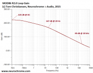
Hopefully, we can put this one to bed now... The results of the loop gain simulation attached.
It turns out the 250 dB that I had in my head was incorrect. The actual number is 225 dB. Sorry about that. I simply misremembered.
The plot shows the total loop gain applied to the LM3886 as function of frequency. The compensation schemes kick in above 100 kHz ensuring a phase margin above 80 º.
Tom
Attachments
Composite amps like this do hell reduce error, similar to adding an integrator in a control system. The whole discussion around the data sheets are getting confusing. But so far what have been covered in the design seem good. What have not been covered probably will not happen in a short time.
- Home
- Vendor's Bazaar
- Modulus-86: Composite amplifier achieving <0.0004 % THD+N.