Well that is what it turned into, by accident... Sometimes you find something new when you don't follow the rules.😉
Well, if you have too much current going through the driver, you add a current path to bypass some so that the driver gets constant current, is there anything wrong with that?
If you want to be taken seriously you have to get the basics right. You cannot 'absorb' current. You can shunt it tho and the laws of physics remain happy.
You may want to look into Norton and Thevenin equivalents. There's no theoretical difference between current drive (Norton) and voltage drive (Thevenin) for the same load impedance.
If you're into current drive, I also suggest looking at Bob Pease's application note, "A Comprehensive Study of the Howland Current Pump". Howland current pumps, such as the MyRef, are notorious for instability and need precisely matched components to ensure stability.
~Tom
If you're into current drive, I also suggest looking at Bob Pease's application note, "A Comprehensive Study of the Howland Current Pump". Howland current pumps, such as the MyRef, are notorious for instability and need precisely matched components to ensure stability.
~Tom
Good 1k Current Source Amp?
I need a SPICE model which accurately sims the evil stuff happening if you don't have a Zobel on the output and the 'real life' to cures for this.
I can do this in 'real life' but not without the complexity of Mills & Hawkesford. 😡
The main reason I'm following this thread is cos I want a simple (eg based on 3886) current source which is at least 1k over the audio range and still allows most of the 3886's power to be used.If you're into current drive, I also suggest looking at Bob Pease's application note, "A Comprehensive Study of the Howland Current Pump". Howland current pumps, such as the MyRef, are notorious for instability and need precisely matched components to ensure stability.
I need a SPICE model which accurately sims the evil stuff happening if you don't have a Zobel on the output and the 'real life' to cures for this.
I can do this in 'real life' but not without the complexity of Mills & Hawkesford. 😡
It seems like classroom material using constant resistance. If you use constant resistance you will get the same result. But if you use driver type varying impedance, you will get different results. This reminds me when I rejected application of a MS in controls. I just looked at his thesis and asked him "why do you use a constant gain to represent a sensor?" the response was "that's what all the books use!" Disqualified.You may want to look into Norton and Thevenin equivalents. There's no theoretical difference between current drive (Norton) and voltage drive (Thevenin) for the same load impedance.
If you're into current drive, I also suggest looking at Bob Pease's application note, "A Comprehensive Study of the Howland Current Pump". Howland current pumps, such as the MyRef, are notorious for instability and need precisely matched components to ensure stability.
~Tom
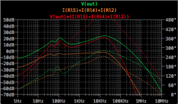
Yes, I have studied the Howland Current Pumps while playing around with the MyRef. It did not seems to satisfy my needs... anyway, I have something that seems to be working better than pure voltage. Below is a simple sim.
I think trying to get a perfect working spice model is not possible. When I asked about the LM3886 spice model, TI recommended I use the LM3876 model.The main reason I'm following this thread is cos I want a simple (eg based on 3886) current source which is at least 1k over the audio range and still allows most of the 3886's power to be used.
I need a SPICE model which accurately sims the evil stuff happening if you don't have a Zobel on the output and the 'real life' to cures for this.
I can do this in 'real life' but not without the complexity of Mills & Hawkesford. 😡
Attachments
Last edited:
Note that the current phase is not what you would get out of a Howland current pump. But it is what is necessary to get better phase linearity of the system.
Why to use Zobel network anyway? 🙂
There is more elegant way with one small value resistor at AMP output!
Enormous number of amplifiers use Zobel network in order to get few percent more power at output (of course also for stability) but with resistor and some mid range power amplifiers (<100W), loses at resistor is in a range of few Watts at maximum power and in general do not make any difference but gives you more predictive and stable FB loop control and much easier to implement, simple pick some stock values resistor instead winding custom inductor!
PS hint: BatoMM amplifier!
PS2: BatoMM is stable with capacitive load up to incredible 8uF due such approach! Don't try such large capacity load with yours amplifier if they don't have such implementation, you will kill you amp in a few second!
More readings in Douglas Self's book, find section "The Output Inductor Value"
https://books.google.rs/books?id=TL...age&q=amplifier without zobel network&f=false
Also watch this nice educadinal video from Analog Devices:
https://www.youtube.com/watch?v=QHIninAg4Is
Is there a validated LTspice *.ASC with good device models for this incredible beast?PS2: BatoMM is stable with capacitive load up to incredible 8uF due such approach!
The stuff at batomm-amp-lm-bridge-consider-try isn't very useful. 🙁
@kgrlee
At a moment I don't have it as it is very hard to make "real" model (not impossible) which will include all parasitics in it and which are highly dependent on practical implementation.
Try basic schematic if you are interested in general overview …
At a moment I don't have it as it is very hard to make "real" model (not impossible) which will include all parasitics in it and which are highly dependent on practical implementation.
Try basic schematic if you are interested in general overview …
Last edited:
I think Douglas Self's book provides some interesting information. From a listening point of view, I have always found that having Zobel in the high frequency region to result in smoother music reducing fatiguing sound which is not hear when listening to live performance without amplification. I have also experienced tweeters which have a flat impedance like a resistor, which according to his book actually not the best load? But these are probable some variables to consider.
I need a SPICE model which accurately sims the evil stuff happening if you don't have a Zobel on the output and the 'real life' to cures for this.
Try using the SPICE Model which uses solder, and grab a network analyzer.
Why to use Zobel network anyway? 🙂
There is more elegant way with one small value resistor at AMP output!
Enormous number of amplifiers use Zobel network in order to get few percent more power at output (of course also for stability) but with resistor and some mid range power amplifiers (<100W), loses at resistor is in a range of few Watts at maximum power and in general do not make any difference but gives you more predictive and stable FB loop control and much easier to implement, simple pick some stock values resistor instead winding custom inductor!
https://www.youtube.com/watch?v=QHIninAg4Is
Just to clear things up, the inductor is a Thiele network, not a Zobel. Which do you actually mean and what are you putting them in for?
Have you got a "basic schematic" of BatomanMM in LTspice?Try basic schematic if you are interested in general overview …
Thanks for your advice jackinnj. I've searched for network analysers on eBay but they are a bit out of this beach bum's budget 😡
It's for a test instrument which is why the 1k needs to be maintained up to 20kHz at high power.
Try using the SPICE Model which uses solder, and grab a network analyzer.
+1
The LM3886 model on the TI website is actually pretty decent. It's not perfect and it does have some rather obvious flaws (such as the lack of modeling anything related to the power supply), but it gets you pretty close. It helps if you include layout parasitics and the parasitics of the passive components.
In the end, there's no substitute for reality, though. A HP 3577A with an injection transformer and a couple of oscilloscope probes are invaluable.
~Tom
the LM3886 gain intercept frequency is well within the range of the Digilent Analog Discovery DAQ - $280 msrp
http://www.digilentinc.com/Products...ac5b6820f-119C0970-5056-0201-025776069788792C
http://www.microchipdirect.com/ProductSearch.aspx?Keywords=TDGL023
http://www.eevblog.com/2014/12/13/eevblog-692-digilent-analog-discovery-review/
http://www.digilentinc.com/Products...ac5b6820f-119C0970-5056-0201-025776069788792C
http://www.microchipdirect.com/ProductSearch.aspx?Keywords=TDGL023
http://www.eevblog.com/2014/12/13/eevblog-692-digilent-analog-discovery-review/
Last edited:
Do you know if it models what happens if you remove the Zobels and the other stuff you explore at lm3886-effect-compensation-network-cc-rf2-cf?The LM3886 model on the TI website is actually pretty decent. It's not perfect and it does have some rather obvious flaws (such as the lack of modeling anything related to the power supply), but it gets you pretty close. It helps if you include layout parasitics and the parasitics of the passive components.
Good 'real life' stuff on your part, BTW 🙂
And can you use it in LTspice?
_________________
Thanks for the links jcx. Is this your recommendation for a cheap scope? A quick glance suggests it hasn't got a trigger function.
This beach bum really needs to get a scope if he is to keep up his pretence of being a guru on the net 🙂
I miss having a nice Tektronix as in my previous life but that was last Millenium 🙁
Last edited:
Do you know if it models what happens if you remove the Zobels and the other stuff you explore at lm3886-effect-compensation-network-cc-rf2-cf?
The AC behavior is modeled well if you include the parasitics of the passives around the LM3886. The clipping behavior is not well modeled. Specifically, I suspect there's a saturation clamp within the LM3886 which tends to oscillate a bit. You see this in real life, but only occasionally in simulation.
~Tom
the last link is EEVblog video of the capabilities (if you can stand the annoying accent) - but while it just gets high enough to give OK stability measurement for the LM3886 it really doesn't go high enough for a MOSFET PA since you really want to see at least a few octaves beyond the loop gain intercept frequency
Rigol has cheap new 'scopes - good value for the $
Rigol has cheap new 'scopes - good value for the $
Last edited:
- Home
- Vendor's Bazaar
- Modulus-86: Composite amplifier achieving <0.0004 % THD+N.