If by ribbons you were referring to tweeters you can wind a ferrite trafo for yourself to transform the impedance to something a bit more amenable to the LM.
Good luck finding core materials that will allow for THD matching that of the MOD86...
~Tom
Good luck finding core materials that will allow for THD matching that of the MOD86...
~Tom
Good luck finding any speaker technology for that matter.
🙂 Well I think we can mark the amplifier as 'transparent' and not worry about upgrades.
I've looked at the data sheet and if you assume a linear increase of dissipation as impedance goes down (holds 8-6-4Ohms) then with 22.5v rails I'd get a max of 40W dumping into the heatsink. I won't have much current in reserve, but I'll take that risk.
I've looked at the data sheet and if you assume a linear increase of dissipation as impedance goes down (holds 8-6-4Ohms) then with 22.5v rails I'd get a max of 40W dumping into the heatsink. I won't have much current in reserve, but I'll take that risk.
Personally, I had no worries pushing the LM38xx. Tightly regulated, I ran mine on rails above 40V, with highly efficient heatsink, for years into a classic 2-way crossover, at full volume for extended periods - no problems.
That fig. 33 is showing you achievable power level for a certain distortion, not what the unit can pump out. If one does everything to make the life of the chip as comfortable as possible, by feeding it excellent voltage rails, and dissipating the heat as effectively as possible then it may do better than one may think it can achieve ...
'excellent voltage rails' You sound like the maitre d'hotel at some overpriced restaurant. You could make a fortune as copywriter for cable manufacturers.
No, that's not silly BS - it means what it says: the voltage level is extremely tightly controlled, it has to be or the max ratings for the chipamp would be exceeded, I wasn't interested in playing chicken. So, irrespective of what the mains voltage was flapping around doing, and how much power was being drawn the rails were locked onto the specified voltage - the term is "regulation", 🙂 . Plus, by most standards extreme levels of very tightly integrated decoupling was in place - up to many 100's of kHz the impedance of the PS was excellent.
My chipamp was actually a power supply ... which just happened to have a minor participant, an LM38xx doing some amplifying duties - that was the approach I used.
My chipamp was actually a power supply ... which just happened to have a minor participant, an LM38xx doing some amplifying duties - that was the approach I used.
Last edited:
Good luck finding core materials that will allow for THD matching that of the MOD86...
Have you measured the THD of the Mod-86 when connected to a real speaker, at the speaker end of the cable?
My chipamp was actually a power supply ... which just happened to have a minor participant, an LM38xx doing some amplifying duties - that was the approach I used.
Whereas I am using a circuit with far higher PSRR than that 3886 on its own (thanks Tom) so I don't have to sweat that.
To be clear, I'm running low rails active. So I'm not throwing away 5dB in the crossover. I don't need huge power. And even if limited to 30W into 3Ohms I'll hit 97dB on the sofa and memsahib will complain.
But this is unchartered waters so some empirical testing is needed.
Good luck finding any speaker technology for that matter.
True.
My chipamp was actually a power supply ... which just happened to have a minor participant, an LM38xx doing some amplifying duties - that was the approach I used.
I've noticed something about amplifier projects. If you can't turn it into a power supply project, you're doing something wrong. The MOD86 is the first amplifier I've designed that's really quite indifferent to the power supply (within reason).
~Tom
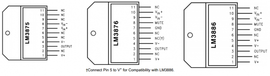
I recall somebody asking a while back if the Modulus-86 board could be used with an LM3876. According to the data sheet, it should work just fine, but it's always nice to try it out in the lab.
I'm pleased to report that the LM3876 can be used in the Modulus-86 board. I've taken a couple of spot measurements and checked the stability. It performs well. The THD is the same low 1.8 ppm as with the LM3886 (@ 1 kHz).
The LM3876 offers better SNR but also lower output current drive compared to the LM3886.
~Tom
LM3875 can be used too? Without pin 5, of course.
Anyone assembled Toms boards? Feedback is what we want to hear 🙂
Anyone assembled Toms boards? Feedback is what we want to hear 🙂
LM3875 can be used too? Without pin 5, of course.
Comparing the pinouts in the data sheets, it quickly becomes rather obvious that the LM3875 and LM3876/LM3886 are NOT pin compatible.
The LM3876 and LM3886 are pin compatible, provided that Pin 5 is connected to VCC on the PCB.
~Tom
Attachments
Last edited:
I was wondering what others are experiencing upon power up, is it a quiet turn on or is there a click, pop, etc.?
I'm not experiencing any pops or clicks at startup or shutdown. I sized the mute resistor to prevent that from happening... 🙂
~Tom
~Tom
- Home
- Vendor's Bazaar
- Modulus-86: Composite amplifier achieving <0.0004 % THD+N.