I've just started a build thread over on the chip amps forum.
...and here is the link to that thread: http://www.diyaudio.com/forums/chip-amps/267802-modulus-86-build-thread.html#post4181355
Thanks for getting the build thread going. It's always good to see my circuits in action.
~Tom
Not sure if this has been asked already (perhaps you should post a FAQ), but what could have been gained/lost if you chose to use an LM4780 instead of an LM3886?
With the two channels in the LM4780, you have two options: Bridge and parallel. Bridging will limit you to 8 Ω*loads as the package cannot handle the thermals involved with a 4 Ω load. Also for bridging, each half of the LM4780 will "see" half the load impedance, hence, operate into a 2 Ω load with a 4 Ω speaker connected. This is not a recipe for anything good.
Therefore, I have chosen to develop a board that uses the two channels of the LM4780 in parallel. This circuit will be able to drive 4 Ω speakers with ease. It will also be able to handle the thermals should one decide to go for a 50 W (8 Ω), 100 W (4 Ω) amp by running on ±35 V. Now, physics haven't changed, so a sizable heat sink is still needed, but there will be more margin in the thermal budget.
With the differential input of the Parallel-86, it will be trivial to bridge two modules for even higher output powers.
Best to say watch this space.
Yep. That is the best. Also keep an eye on my website.
what I don't know is if the 4780 is thermally limited that will limit the potential advantages.
You can fish out some clues from this thread: http://www.diyaudio.com/forums/chip-amps/265771-lm3886-thermal-experiment-data.html
~Tom
You can fish out some clues from this thread: http://www.diyaudio.com/forums/chip-amps/265771-lm3886-thermal-experiment-data.html
~Tom
1.2dB extra power. More than a gnat fart that's for sure 🙂
The thermal resistance of the LM4780 is a tad lower - 0.8 K/W vs 1.0 K/W for the un-isolated LM3886. That helps a bit. The LM4780 package is smaller than two LM3886es, so you don't get the full benefit, but its a pretty nice package regardless. The two notches for screw mounting on the LM4780 also makes it easier to get good clamping pressure distributed evenly across the package.
Physics is still physics, though. With a parallel amp running flat out, large amounts of heat is dissipated in the package. A large heat sink is needed!
~Tom
Physics is still physics, though. With a parallel amp running flat out, large amounts of heat is dissipated in the package. A large heat sink is needed!
~Tom
I've persuaded myself not to chase the last watts this time round, although I did get as far as looking to lap the package to the spreader before I realised I was getting obsessed 🙂
The thermal resistance of the LM4780 is a tad lower - 0.8 K/W vs 1.0 K/W for the un-isolated LM3886. That helps a bit. The LM4780 package is smaller than two LM3886es, so you don't get the full benefit, but its a pretty nice package regardless. The two notches for screw mounting on the LM4780 also makes it easier to get good clamping pressure distributed evenly across the package.
True, but LM4780 is not available as insulated unit, so insulator is must. Also, it is not easy to get a decent low thermal resistance insulator such a big size as LM4780 is.
Physics is still physics, though. With a parallel amp running flat out, large amounts of heat is dissipated in the package. A large heat sink is needed!
How big heatsink would be needed? Something between 0.4 - 0.5 K/W per IC?
True, but LM4780 is not available as insulated unit, so insulator is must. Also, it is not easy to get a decent low thermal resistance insulator such a big size as LM4780 is.
An insulating thermal pad is a must. I buy a sheet of SilPad 1500ST from Mouser. The sheet is probably 20x30 cm and costs about $30. So a bit spendy for a single project, but the stuff will keep you going for many projects.
How big heatsink would be needed? Something between 0.4 - 0.5 K/W per IC?
I'll have to do the math. For continuous operation with a sine wave at the peak power dissipation, 0.4-0.5 K/W sounds reasonable for an external heat sink. For music reproduction, you can probably get away with less.
As you can see in my LM3886 Thermal Experiment (with data) thread, it is actually just barely possible to run an LM4780 with the two channels in parallel at the peak power dissipation into a 4 Ω load on a Pentium Pro heat sink (2 K/W). I would not recommend that as the heat sink reaches over 100 ºC under these conditions and the chip operates at the edge of thermal shutdown.
~Tom
An insulating thermal pad is a must. I buy a sheet of SilPad 1500ST from Mouser. The sheet is probably 20x30 cm and costs about $30. So a bit spendy for a single project, but the stuff will keep you going for many projects.
Before National was purchased by TI I spoke with them about this issue -- there doesn't seem to be any pad in the Bergquest catalog which works with these devices. I did have a company in China which would have used a die to cut them, but would need about 5 to 10 thousand be made.
They could probably be cut by my company's laser, but 2.5kW would obliterate a lot of material.
Um, by my understanding that means yes, not no.Um, no. The harmonics are 115 dB below the fundamental, hence, the 0.00018 % (1.8 ppm) THD.
The error signals are suppressed by the loop gain of the amplifier. At DC, the loop gain of the Modulus-86 is about 250 dB. At 20 kHz, the loop gain is 47 dB, rolling off at -20 dB/dec.
~Tom
You are saying that the loop gain (the difference between the open loop gain and the feedback) is 47dB @ 20kHz.
That means an error signal, or unwanted harmonic, is suppressed by 47dB @ that frequency.
You are confirming that the 20kHz error is not suppressed by 115dB.
http://www.diyaudio.com/forums/atta...d1421026360-modulus-86-build-thread-board.jpg
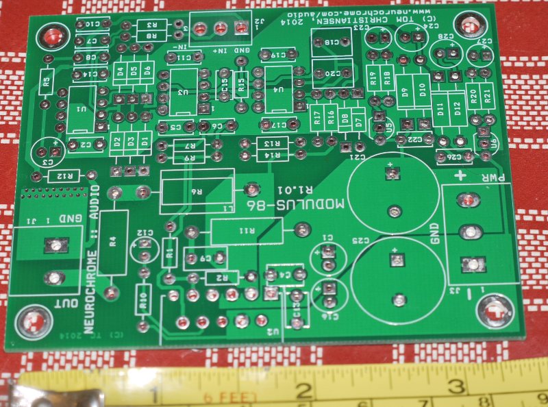
On this pic you can see some of the detail in routing pairs of traces together.
Neat !
On this pic you can see some of the detail in routing pairs of traces together.
Neat !
Um, by my understanding that means yes, not no.
I have no idea what you're trying to say there.
You are saying that the loop gain (the difference between the open loop gain and the feedback) is 47dB @ 20kHz.
That means an error signal, or unwanted harmonic, is suppressed by 47dB @ that frequency.
That is correct.
You are confirming that the 20kHz error is not suppressed by 115dB.
In Post #729, you claim that the maximum suppression available at "LF" (however you define that) is 115 dB. That claim is false.
My claim is that the harmonics are 115 dB below the (1 kHz) fundamental. This is well documented by the THD plots I have posted.
~Tom
well to my mind if the second harmonic of 10KHz is suppressed 47dB I'll take that as inaudible. last time I tried to hear a 20KHz tone I burned out a tweeter.
If the offending harmonic was 68dB below the fundamental to start with, and we applied 47dB of feedback at the harmonic frequency, the harmonic would end up 115dB below the fundamental.
"Reduced to -115dB" is not the same thing as "reduced by 115dB", because the circuit has a certain amount of linearity when running open loop.
"Reduced to -115dB" is not the same thing as "reduced by 115dB", because the circuit has a certain amount of linearity when running open loop.
"Reduced to -115dB" is not the same thing as "reduced by 115dB", because the circuit has a certain amount of linearity when running open loop.
My point exactly.
Ribbons refitted and have realised that I am going to be right on the limit as they measure 3.1 Ohms. Looking at fig 33 of the datasheet the power delivery is dropping like a stone at that point, but I should still get the 40W I need...I hope.
You'll be limited mostly by the thermals, but yeah... 3 Ω is a bit marginal for an LM3886. Need two in parallel for that.
~Tom
~Tom
If by ribbons you were referring to tweeters you can wind a ferrite trafo for yourself to transform the impedance to something a bit more amenable to the LM.
- Home
- Vendor's Bazaar
- Modulus-86: Composite amplifier achieving <0.0004 % THD+N.