I apologize for being human.
Being human means admitting to mistakes, not pretending they didn't occur and deflecting attention from them.
I'll take your 4 kΩ load at face value.
Far better that you'd check for yourself, after all I'm no authority here.
That's still only around 800 µA peak output current for the THAT (including the 90 µA that goes into the LME49710).
You're making several more errors here. The output current is not much of an issue, since you've pointed out its less than the standing current in the OPS. The issue is the internal loading on the various opamps due to the internal resistors (in the main 6kohms). Perhaps better for you to do the math in the cold light of day, no?
How have you arrived at the 800uA figure? Do please show your working.
Even if the THAT was operating in Class B (not AB), that would still only lead to 8 µV of bounce on the supply.
Based on what - the claimed 10mohm output impedance of the regulator? Is that right across the frequency band and flat? How does the regulator respond to noise imposed on its output? Any data on that? What about data of the PCB track impedance (both inductance and resistance) between the regulator and the THAT?
That would result in 0.635 nV on the THAT and 6.35 nV on the output of the MOD86. That's -164 dBV or 39 dB below the ultra low -125 dBV noise floor.
More irrelevance.
There's no issue there. None.
Looks to me like another faith-based claim. Ironic no given what peufeu remarked on earlier? 😀
...........
I'd be interested in the ABX results if you have a link. Whilst there are pages upon pages nearly all of them are sighted "tests" without much, if anything, in the way of controls.
Sure, coming right up 😀😀

Exactly. Feed that into a 105dB SPL/W horn and the output sound level would be -65 dB SPL W/m 2uPa. If the compression driver was just about ideal and had no meaningful friction. That's way below the threshold of human detection and even further below the 30 or 40 dB SPL typical of quiet ambient noise floors.More irrelevance.
So why all the fuss about the details of exactly how irrelevant this is? Seems to me the energy might be more usefully devoted to a separate thread on op amp implementation details.
Well, if you push a polypro to really crappy operating point the THD might get above -125dB. In the data I've come across C0G, PPS, PET, PEN, and audio signal path electrolytics like Elna RFS all seem to measure in the -140 to -130dB range in typical audio operating conditions.
Douglas Self explored this some in his "Small Signal Audio Design" book. He was looking specifically at coupling caps in pro audio circuits, so +4 dBu (1.2 V RMS) signal level (AFAIR) into a high-pass filter. His conclusion was that electrolytic caps increased the distortion levels near the cutoff frequency. Hence, if one designs for a 2 Hz cutoff to avoid phase change in the audio band (>20 Hz), one ends up with "significant" distortion in the audio band. "Significant" here means the THD was, maybe, 10x above the noise floor of the Audio Precision System Two he was using for the measurement (0.0005 % THD floor, 80 kHz BW). His solution to this was easy: Increase the capacitance such that the corner frequency moves well below the audio band. Given the cap density of electrolytic caps, this is pretty easy...
I recall there being minute differences between the other dielectrics as well. It wasn't anything earth shattering. I do recall that polypropylene, polyester, and (I think) polystyrene caps were among the top performers. Polystyrene (Styrofoam) caps aren't used much anymore. Turns out they don't really like the acetone used in the flux cleaners... Who would have thought... 🙂
I'm sure you can drive any component into an undesired operating point and get the circuit to misbehave. My approach is to learn the limitations of the components and design the circuit such that the components operate well below their limits and well within their optimal operating region.
Exactly. Feed that into a 105dB SPL/W horn and the output sound level would be -65 dB SPL W/m 2uPa. If the compression driver was just about ideal and had no meaningful friction. That's way below the threshold of human detection and even further below the 30 or 40 dB SPL typical of quiet ambient noise floors.
So why all the fuss about the details of exactly how irrelevant this is? Seems to me the energy might be more usefully devoted to a separate thread on op amp implementation details.
I wholeheartedly agree. Besides, USPS claims that I will be taking delivery of a Connex Electronic SMPS300RE today. My crystal ball forecasts a busy night in the lab... I should get a test plan together.
~Tom
Last edited:
That's in line with other measurements of polar caps that are starting to get cranky I've come across; -105dBish THD. Spent a bit trying to dig up the RFS measurement data I came across a few years ago. But no love."Significant" here means the THD was, maybe, 10x above the noise floor of the Audio Precision System Two he was using for the measurement (0.0005 % THD floor, 80 kHz BW).
Eh, I'd go with a THAT 1200 for level translation. Rejection's maintained above 1Hz, it's more compact on the board (so cost is roughly a wash), ya don't have to futz to get that extra zero in the THD, and no cap matching hassles. More noise than a C+R||C bandpass but it ends to be hidden in the RMS sum by other parts of the circuit.
Exactly. Feed that into a 105dB SPL/W horn and the output sound level would be -65 dB SPL W/m 2uPa. If the compression driver was just about ideal and had no meaningful friction. That's way below the threshold of human detection and even further below the 30 or 40 dB SPL typical of quiet ambient noise floors.
You lost me here. Where was the evidence for the original claim, I must have missed it? For reference that was the '8uV of supply bounce' one.
Fuss? Another faith-based claim perchance? 😀So why all the fuss about the details of exactly how irrelevant this is? Seems to me the energy might be more usefully devoted to a separate thread on op amp implementation details.
Last edited:
I think from my reading of D.Self that he concluded that by moving the turnover (F-3dB) frequency of the passive high pass filter to around 2Hz, that he had attenuated the avoidable in band distortion contributed by the electrolytic to a low enough level. The electrolytic he is referring to is the NFB DC blocking cap. D.Self shows RC combinations of ~100ms, giving F-3dB=1.6HzDouglas Self explored this some in his "Small Signal Audio Design" book. He was looking specifically at coupling caps in pro audio circuits, so +4 dBu (1.2 V RMS) signal level (AFAIR) into a high-pass filter. His conclusion was that electrolytic caps increased the distortion levels near the cutoff frequency. Hence, if one designs for a 2 Hz cutoff to avoid phase change in the audio band (>20 Hz), one ends up with "significant" distortion in the audio band. "Significant" here means the THD was, maybe, 10x above the noise floor of the Audio Precision System Two he was using for the measurement (0.0005 % THD floor, 80 kHz BW). His solution to this was easy: Increase the capacitance such that the corner frequency moves well below the audio band. Given the cap density of electrolytic caps, this is pretty easy... ......................
This avoidable distortion can be further reduced by ensuring the input high pass filter is set to a higher frequency than the NFB, i.e. set the input filter (film cap) to ~1.5Hz and set the NFB to ~1Hz.
This two passive filter topology ensures that the AC signal across the NFB DC blocking cap is insignificant.
Last edited:
I'm curious, interested perhaps, about aquiring one of these Modulus creations.
I have what sounds like a Good 3886 amp, from Daniel Joffe. (as a DIY gut/refill of an old Dyna St120 chassis)
It works well. Far Better (to my complete Surprise) than my twin amp Arcam setup.
Problem is; it's effing up. Currently making a Scrotch sound thru the speakers on power up... every single time..even with Nothing other than speakers connected.
Not an auspicious sound effect.
Time for a replacement.. quickly.. perhaps even a trip to the dustbin.. Methinks.
Only wanting a Good to Very good performing amp...that will live long ??
Simple needs and expectations ?
Have a pair of 200 W 28 V +- smps gizmos intended for a VSSA amp build, currently sidetracked by the usurious pricings of a prefabbed box/ chassis, not even a good one at that.. grrr
Does one have to DIY..everything?
Presumably 28 V is adequate to needs?
Have a pair of 200 W 28 V +- smps gizmos intended for a VSSA amp build, currently sidetracked by the usurious pricings of a prefabbed box/ chassis, not even a good one at that.. grrr
Presumably 28 V is adequate to needs?
±28 V would be perfect for the Modulus-86. ±24~±28 V is the sweet spot in the tradeoff between higher output power and reasonable heat sink sizing.
Does one have to DIY..everything?
Not necessarily... I'll be happy to save you the trouble of optimizing your own PCB layout by selling you a pair of boards, for example.... 😉
~Tom
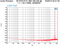
The long-awaited 19k+20k IMD measurements are done and attached to this post. Note that the IMD of the AP SYS-2712 itself is actually responsible for most of the IMD measured on the Modulus-86.
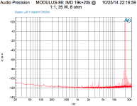
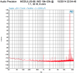
The first plot shows the IMD of the AP itself. I used the generator monitor to measure the IMD of the generator and analyzer combined. The two other plots show the IMD of the Modulus-86 (and the AP). Comparing the loopback test to the tests of the MOD86, by comparing the relative amplitudes of the two stimulus frequencies and the various IMD products, reveals that the 13k, 14k IMD components are up about 5 dB to 125 dB below the stimulus amplitude and the IMD components at 16k, 17k, 21k, and 22k are up about 10 dB. The worst offenders are around 105 dB below the stimulus signal. That's 0.00056 % IMD.
Aside from some 60 Hz related components, some 135 dB down from the stimulus at 19k+20k, I'm not noticing any meaningful difference between the performance of the Modulus-86 on the lab supply versus unregulated supply.
This is pretty darn good if you ask me.
~Tom
Attachments

I use 1 oz (35 um) copper. Given the size of the board and the way the layout is optimized, there's really no need for thicker copper.
~Tom
~Tom
Hello TOM,
a friend of mine point me out you thread, and I just want to SAY : "CONGRATULATION" for your JOB.
I appreciate your work, because I've been working on a similar concept for ages. unfortunately, my skills are not close to yours, and the project never ended up on my side (instabilities ....).
(Links in French .... 😛)
The first project initiated in 2011 !!!
THE NAME OF THE PROJECT WAS "FAST BACK" ... You see what I mean !
Un nouvel ampli DIY - FastBack sur le forum Amplification du site Homecinema-fr.com - 29959864 - 1056
the second project was :
Le "FastTrack 50W" ... LM3886+AOP en config Compound sur le forum Amplification du site Homecinema-fr.com - 30049102 - 1056
Additional elements :
Gain Clone ? Projet LM3886 « GD » sur le forum Amplification du site Homecinema-fr.com - 30031948 - 1056
I'm gonna read your thread, and will post questions.
First question : Do you envisage an asymmetric circuit and a Single board with 2 parallel LM3886?
My initial plan was to create a PA100 equivalent Amplifier that could drive any Speakers with an extremely low distortion.
Another time : "FELICITATIONS" FOR YOR GREAT WORK!
Cheers Gilles.
Hi Tom,
How does it perform under a 4R speaker load? I'm asking since your graphs are all done under 8R. What would be the ideal supply voltage under 4R and expected output power?
Thanks
Do
How does it perform under a 4R speaker load? I'm asking since your graphs are all done under 8R. What would be the ideal supply voltage under 4R and expected output power?
Thanks
Do
Hello TOM,
a friend of mine point me out you thread, and I just want to SAY : "CONGRATULATION" for your JOB.
I appreciate your work, because I've been working on a similar concept for ages. unfortunately, my skills are not close to yours, and the project never ended up on my side (instabilities ....).
Thank you for your kind comments. As you've found, a composite amplifier can be a tricky beast to get to work correctly. Considerable effort was put into my design to ensure that it would work well in the hands of my customers.
First question : Do you envisage an asymmetric circuit and a Single board with 2 parallel LM3886?
My initial plan was to create a PA100 equivalent Amplifier that could drive any Speakers with an extremely low distortion.
I've had thoughts along those lines. Either two LM3886es in parallel or the two sections of an LM4780 in parallel. The LM4780 would probably offer a cleaner layout, but worse thermal performance than the LM3886 as the LM4780 package is not that much bigger than that of a single LM3886.
Meanwhile, you can connect two Modulus-86 boards in parallel to drive high-current loads.
How does it perform under a 4R speaker load? I'm asking since your graphs are all done under 8R. What would be the ideal supply voltage under 4R and expected output power?
For a "universal" amplifier capable of driving a 4Ω and/or 8Ω load, I'd stick to ±28 V or below. ±24 V is just about perfect. Voltages down to ±20 V are supported in the Modulus-86.
The THD+N with 4 Ω load is slightly higher than with 8 Ω. We're talking something like 0.0008 % vs 0.0006 % or similar. It performs well until it hits the thermal protection limit of the LM3886 (see more below). I have not done extensive testing at 4 Ω as I still need to sort through the thermal limitations of the LM3886. I don't expect any meaningful difference in the measured performance with 4 Ω load for the Modulus-86, however.
All my testing so far has been with the isolated version of the LM3886 (LM3886TF, to be precise). Once you hit about 30-35 W with a 4 Ω load, the SPiKe protection engages because the IC is overheating. If you are to drive a 4 Ω load, you really need to use the non-isolated LM3886T or multiple LM3886TFs in parallel. This presents new complications. Either you need to find a thermal pad that will fit the package and provide good thermal performance (this is no easy task) or you will need to mount the IC directly to the heat sink with only thermal grease between the IC and the heat sink. This connects the heat sink to VEE, which presents other challenges.
As you can see, this is a multi-variable optimization problem and it snowballs really fast. I have an experiment planned to sort through these issues: LM3886T, LM3886TF, and LM4780T. I will characterize the thermal performance of these chips and figure out where to go from here. The results will be posted in a separate thread in the Chipams forum (and on my Taming the LM3886 website).
~Tom
Hello Tom,
Thanks for your answer.
I've few additional question related to your schematic. I do not know really what is the exact schematic you have done, however on my side I've studied differents AOPs.
Originally I was using the LME49710 (as well as you). but looking into the specs of others AOPs, I've seen that the OPA227/OPA228 could do the job even better. the OPA227 or 228 are a bit less optimal for distortion, however they outperform for Offset, CMRR , drift ... So the use of the OPA could avoid the DC Servo. On top of that using the AOP in an inversing mod, shows on my demoboard a 0mV offset, without any SERVO.
As I said, i do not know exactly what you've done.... So ...
I'm also really interrested with what you wrote about the SPIKE. When i sait that my system was instable, I mean that when the spikes activates ... then the system cannot be controlled. on my side I 've a +35/-35V PSU, and I test up to ... >> 50watts with a single 3886 in a 6.8 Ohm load.
http://www.homecinema-fr.com/forum/...3886-aop-en-config-compound-t30049102-30.html
So my question is , What happen when you reach the limit and the spikes activates itslef. Is your system comeback to normal automatically ?
(on my side, the AOP compensate the spikes, and then we go into oscillations).
On my side I was able to go up to 135W (for few secs), and then after the chip increase in temperature, then after the system auto oscillate even if I was reducing the input signal getting into the amplifier.
thanks for your feedback.
Regards Gilles.
Last edited:
Member
Joined 2006
- Home
- Vendor's Bazaar
- Modulus-86: Composite amplifier achieving <0.0004 % THD+N.