No worries. The toroid I used was actually a 530 VA, 2x35 VAC one I picked up in the late 1990ies to use in a 100 W amp. I used a variac on the primary to adjust the primary voltage such that the supply delivered +/-28 V DC across the supply caps.
As mentioned in Post #199, the Modulus-86 contains two low-noise regulators creating +/-15 V for the opamps on the board. I wanted the board to be self-contained and easy to use, hence, used on-board regulation.
~Tom
As mentioned in Post #199, the Modulus-86 contains two low-noise regulators creating +/-15 V for the opamps on the board. I wanted the board to be self-contained and easy to use, hence, used on-board regulation.
~Tom
Terrences
He means you need a transformer with dual secondaries. So 4 wires on secondary side. Each pair of wires offers a voltage and each pair gets its own rectifier.
He means you need a transformer with dual secondaries. So 4 wires on secondary side. Each pair of wires offers a voltage and each pair gets its own rectifier.
Thanks for trying to clear this up udaily. It's kind of confusing because he could get the half rails from the same trafo or he could just slam the 22VAC down with the regulator. If the controlling op-amps could run with +/-12V then I would consider batteries with a charging circuit for the whole amp. Tom, I suppose it doesn't matter how you got the two different voltages but I was interested only to the extent that it may highlight the excellent PSRR of your design. Batteries have no ripple but they do make noise, could they possibly get the amp does to -120dB throughout the audio band or are the chips the noise floor limit?
Question to the Designer
Tom,
Soundwise, what amp would you choose considering :
- sound stage and holographic sound reproduction
- listning plesure with low volume level ( 70-76 dB), with word "plesure I mean lack of sibilances with female vocals , good timing , tight bass
if building costs were not taken into the account
Modulus
or
Damn Good 300 B
thank you in advace for the answer
Thanks for trying to clear this up udaily. It's kind of confusing because he could get the half rails from the same trafo or he could just slam the 22VAC down with the regulator.
This is the schematic I posted in Post #125. This is what I'm using for the lab testing. Variac omitted for clarity.
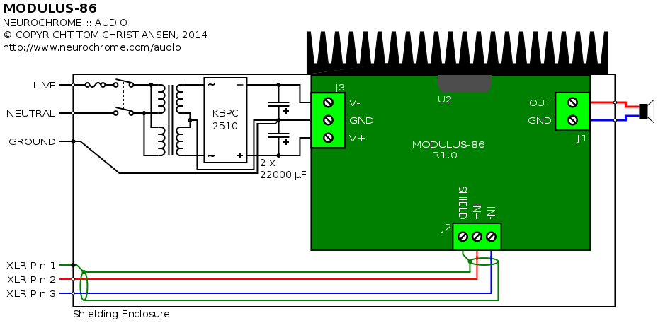
In my final build, I'll use a Connex Electronic SMPS300RE.
Tom, I suppose it doesn't matter how you got the two different voltages but I was interested only to the extent that it may highlight the excellent PSRR of your design.
I think the excellent PSRR of my design is already highlighted by the fact that the Modulus-86 performs just as well on a real supply (transformer + rectifier + cap) as it does on a pair of $1200 well-regulated lab power supplies. That's been documented in the THD+N plots already. I do plan to do a better job at presenting that data, however.
Batteries have no ripple but they do make noise, could they possibly get the amp does to -120dB throughout the audio band or are the chips the noise floor limit?
Are you talking about -120 dB THD? Or -120 dBV noise floor. I'm confused here. The Modulus-86 measures to -115 dB THD (0.00018 %) at 1 kHz, 35 W, 8 Ω. The noise floor measures -125 dBV. The THD is limited at LF by the THAT1200 and at HF by the loop gain of the composite amp.
Batteries have the annoying habit of discharging over time. That's how they operate... You need to make sure that the circuit shuts down gracefully when the supply voltage to the error-correction opamp and DC servo collapses. If you build in a charging circuit, you also need to ensure that the charging circuit is disconnected from the active circuitry on start-up. Both of those design requirements sound easy, but actually represent significant design challenges.
~Tom
Last edited:
Soundwise, what amp would you choose considering :
- sound stage and holographic sound reproduction
- listning plesure with low volume level ( 70-76 dB), with word "plesure I mean lack of sibilances with female vocals , good timing , tight bass
if building costs were not taken into the account
Modulus
or
Damn Good 300 B
That's a really good question. Right now, the DG300B is my main amp. This is mostly driven by the fact that the Modulus-86 is still on the lab bench. I'm running with bi-amping and active crossovers on my main setup, so I need four channels of amplification. I have three channels assembled thus far. I need four channels and some more time listening before I can make an (sighted, biased, usual disclaimers apply) A/B comparison.
I tested the Modulus-86 on my Dali 3A speakers with built-in crossovers (upgraded to polypropylene caps) and was very impressed. I have listened to the DG300B on the same speakers back when it was in the prototyping stage.
Modulus-86 vs DG300B... I think that boils down to build budget and personal preferences. Budget aside, I think those who prefer the tight bass and precise transient response of a semiconductor amp would be happier with the Modulus-86, whereas those who prefer the slightly warmer presentation of the DG300B would be more satisfied with the DG300B. For those who prefer the voicing of the 300B, there's no substitute.
The build budget for the Modulus-86 is just shy of $400 including the chassis. A low-end build for the DG300B comes in around $1000~$1100. My DG300B build set me back about $1500 per stereo amp. I'm a little afraid that I might end up liking the Modulus-86 better... Time will tell.
~Tom
Out of curiosity, how would you give this amp a high output impedance, for e.g. a current drive application?
Out of curiosity, how would you give this amp a high output impedance, for e.g. a current drive application?
By changing the architecture such that the amp becomes a current source rather than a voltage source. One such architecture is the Howland current pump. I suggest reading Bob Pease's application note (National AN-1515) on the topic if you're curious about the design challenges and tradeoffs for a Howland current pump.
~Tom
Unfortunately, all the electronics design work I did was many years in university (and I would like to stress that I am a mechanical engineer), so I can't pretend to understand what they're talking about. Practically speaking, is it possible to do effectively using your same boards, perhaps with a daughterboard of some type, or does a new board have to be designed?By changing the architecture such that the amp becomes a current source rather than a voltage source. One such architecture is the Howland current pump. I suggest reading Bob Pease's application note (National AN-1515) on the topic if you're curious about the design challenges and tradeoffs for a Howland current pump.
~Tom
Last edited:
You would have to design a different circuit if you wanted a current source rather than a voltage source. So new board, new stability analysis, new design.
~Tom
~Tom
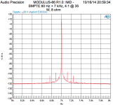
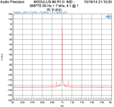
IMD measurements attached. This shows the SMPTE 60 Hz + 7 kHz at a 4:1 ratio. The 7 kHz fundamental and the IMD products are shown. This is quite possibly the only area where the Modulus-86 shows a teeny-tiny bit of difference between using a lab supply and an unregulated supply. The difference is small, however.
Measurements at full output power (35 W) and normal-high listening levels (1 W) for both unregulated and lab supply are shown.
~Tom
Measurements at full output power (35 W) and normal-high listening levels (1 W) for both unregulated and lab supply are shown.
~Tom
Attachments
Last edited:
The even harmonics of the 60Hz seem to be about the same for the two PSUs.
The odd harmonics are very slightly less with the agilent.
I have noticed this with mains harmonics attenuation in a conventional PSU.
The odds are often worse than the evens and 3rd is very often the worst.
Is there some correlation here between IMD and Capacitor input filter?
Could the 60Hz mains be confusing the 60Hz test signal?
What about 70Hz and 7.1kHz as the IMD test signal?
Then this makes me wonder: What If?
What if a simple rC(L+r)CC were implemented as the smoothing in the PSU instead of rCCC?
i.e. just add an air cored home made inductor between first and second smoothing caps.
Is that enough theory and explanation, or will you reject this as well?
Last edited:
That's two observations and four questions. No use of theory or formulation of a testable hypothesis. There's a certain amount of explanation in that the ordering of observations and questions shows the thought process. But nothing as to why it's desirable to degrade supply line and load regulation to try to lower spurs which are 120dB down.
Net net, there's little for a design engineer to action. If you're curious about the interaction between amps and supply filtering have at it in Spice or on the bench. That'll provide context on the system behaviour and data to reason about such that a well informed hypothesis can be developed. Rather than speculating something different might happen if something different were used.
Net net, there's little for a design engineer to action. If you're curious about the interaction between amps and supply filtering have at it in Spice or on the bench. That'll provide context on the system behaviour and data to reason about such that a well informed hypothesis can be developed. Rather than speculating something different might happen if something different were used.
Well... Let's take a look. The IMD products at 180 and 300 Hz offset degrade by 2-3 dB when an unregulated supply is used. The remaining IMD products are from the amplifier itself.
The supply-induced IMD is 10+ dB below all the other spurs, which are 120 dB down from the 7 kHz stimulus and 132+ dB down from the 60 Hz stimulus to start with. There's no issue here, hence, no action is needed.
This measurement speaks volumes to the ultra-high performance of the Modulus-86 amp, both in terms of the IMD performance of the amp and the supply immunity of it.
The analyzer isn't getting confused. It just reports what's on the output of the amp. It's then up to the circuit designer to interpret the result, which is why I provided measurements using both regulated and unregulated supplies.
~Tom
Last edited:
If you want to do stuff like this to really improve performance, you need to read Prof Cherry inWhat if a simple rC(L+r)CC were implemented as the smoothing in the PSU instead of rCCC?
i.e. just add an air cored home made inductor between first and second smoothing caps.
AES E-Library A New Distortion Mechanism in Class B Amplifiers [1]
Those versed in the art will take away many useful and practical pointers to better wiring, layout & decoupling .. even if you don't adopt his methods in full.
Note the importance of Physical placement of bits & wiring.
The fact that tom's measurements show so little difference between conventional supply & supa dupa Agilent .. says his Decoupling, Layout & Grounding is excellent .. though I'd like to see some THD @ 20kHz into load at full power.
[1] BTW, Great Guru Baxandall was talking about these issues in the early 70's so it isn't new .. but Cherry was the first to formalise it.
Last edited:
Just to mention that Cherry's paper is available here, http://www.linearaudio.nl/linearaudio.nl/images/pdf/Cherry mutual inductance distortion.pdf.
Also, would echo a request for IMD with 19k+20k test tones, if possible ...
Also, would echo a request for IMD with 19k+20k test tones, if possible ...
Re. supply filtering: There are a couple of pieces of this puzzle:
So, basically, you need to view the problem from the supply's "point of view" as well as the amp's "point of view".
To get any meaningful filtering of the ripple voltage, an RC or LC supply filter would have to have a cutoff frequency well below 50/60 Hz. This requires an inductor with a significant inductance (50 mH + 22000 uF --> 5 Hz cutoff, for example). The inductor would need to be able to handle the supply current without saturating. This means an expensive and bulky inductor. It also means that the inductor will have significant DC resistance. This, in turn, limits the HF attenuation of the supply filter.
The situation is even worse with an RC filter. The commonly used 0.47 Ω resistor along with a cap with, say, 50 mΩ ESR, will result in only 20 dB of attenuation at HF.
Depending on the Q of the LC supply filter, a transient on the mains (happens all the time) may actually cause the LC to exhibit a bit of ringing. So every time someone turns on a heavy load (fridge, furnace, etc.) the supply voltage will go spoiiinnnggg with a 5 Hz ringing component. That's pretty poor line regulation.
Load regulation: A class AB amp is not a nice load. The two halves of a class AB output stage take turns drawing current from the supply as the output signal swings about zero, hence, the load current (= amp supply current) is a pulse train. Any resistance in series with the supply will exhibit a large voltage drop, thus, any resistance in the supply line will actually make the load regulation worse. If you're thinking about using a CRC filter, you're far better off scrapping the R and putting the two caps in parallel.
Adding a small air core supply inductor (1 uH) will provide no attenuation in the audio band. It will, however, add series resistance. So for audio frequencies, we're back to the CRC filter. Not a good idea...
If you want an amp that provides good performance regardless of any crap on the mains voltage, you either need to use a regulated supply or use an amp with stellar supply rejection. The Modulus-86 is an example of such an amp.
Note: I've been using the terms "line regulation" and "load regulation" to describe the impact of the supply filter. Technically, there is no regulation in an unregulated supply, hence, those terms don't apply. They are, however, the most descriptive terms I can think of.
~Tom
- Mains hum - 100/120 Hz components arising from the rectification itself. Note, the harmonics of the ripple voltage extend into the kHz region.
- Line regulation - the amount of mains variation that feeds through to the output of the power supply.
- Load regulation - how the load (amp) affects the supply voltage.
So, basically, you need to view the problem from the supply's "point of view" as well as the amp's "point of view".
To get any meaningful filtering of the ripple voltage, an RC or LC supply filter would have to have a cutoff frequency well below 50/60 Hz. This requires an inductor with a significant inductance (50 mH + 22000 uF --> 5 Hz cutoff, for example). The inductor would need to be able to handle the supply current without saturating. This means an expensive and bulky inductor. It also means that the inductor will have significant DC resistance. This, in turn, limits the HF attenuation of the supply filter.
The situation is even worse with an RC filter. The commonly used 0.47 Ω resistor along with a cap with, say, 50 mΩ ESR, will result in only 20 dB of attenuation at HF.
Depending on the Q of the LC supply filter, a transient on the mains (happens all the time) may actually cause the LC to exhibit a bit of ringing. So every time someone turns on a heavy load (fridge, furnace, etc.) the supply voltage will go spoiiinnnggg with a 5 Hz ringing component. That's pretty poor line regulation.
Load regulation: A class AB amp is not a nice load. The two halves of a class AB output stage take turns drawing current from the supply as the output signal swings about zero, hence, the load current (= amp supply current) is a pulse train. Any resistance in series with the supply will exhibit a large voltage drop, thus, any resistance in the supply line will actually make the load regulation worse. If you're thinking about using a CRC filter, you're far better off scrapping the R and putting the two caps in parallel.
Adding a small air core supply inductor (1 uH) will provide no attenuation in the audio band. It will, however, add series resistance. So for audio frequencies, we're back to the CRC filter. Not a good idea...
If you want an amp that provides good performance regardless of any crap on the mains voltage, you either need to use a regulated supply or use an amp with stellar supply rejection. The Modulus-86 is an example of such an amp.
Note: I've been using the terms "line regulation" and "load regulation" to describe the impact of the supply filter. Technically, there is no regulation in an unregulated supply, hence, those terms don't apply. They are, however, the most descriptive terms I can think of.
~Tom
Thanks for the links to the articles, by the way. I appreciate it.
The IMD generator in the AP SYS-2700 doesn't support 19k+20k test tones as the LF tone needs to be below 500 Hz. I think there is a way to generate multi-tone files. I'll look into that.
I'm still curious what that measurement will show you, though. Is it an indirect measure for the loop gain at 20 kHz? How does this test the amp beyond what the rest of the tests have done? I'm genuinely curious here. I'll be happy to perform the measurement provided that I can get the AP to produce the two tones.
~Tom
Also, would echo a request for IMD with 19k+20k test tones, if possible ...
The IMD generator in the AP SYS-2700 doesn't support 19k+20k test tones as the LF tone needs to be below 500 Hz. I think there is a way to generate multi-tone files. I'll look into that.
I'm still curious what that measurement will show you, though. Is it an indirect measure for the loop gain at 20 kHz? How does this test the amp beyond what the rest of the tests have done? I'm genuinely curious here. I'll be happy to perform the measurement provided that I can get the AP to produce the two tones.
~Tom
- Home
- Vendor's Bazaar
- Modulus-86: Composite amplifier achieving <0.0004 % THD+N.