Well, it's important not to let the facts get in the way of a good opinion. 😉 More seriously, I think a lot of DIYers simply lack the scientific background to formulate rigorous tests. That's entirely understandable, though I do often find myself wishing folks would take more advantage of existing ABX software tools, the ability of DSP and digital music to easily set up AB manipulations of tracks, and so on. I've found this is rather powerful, both when you get statistically significant discrimination and when you don't.I note no one seems interested in the results of a properly conducted DBLT bla bla that actually comes up with a distinct preference 🙁
A project idea I've had floating around for a while is a DPDT relay board to make ABX hardware testing easy. It's not perfect---muting the relays or ensuring fake switching isn't discriminable from real switching is a problem---but it'd be better than sighted swapping of op amps in sockets at least.
Yes and no. I agree with your point but would say it's worth thinking beyond it as well. As Bruno Putzeys points out, drivers and speakers have energy storage which no test on a linear load will replicate. The problem is there is no standardized, well controlled moving mass kind of load. So we all go back to testing with resistors and obtaining itsy bitsy teeny weeny THD and IMD numbers. These measurements conflate the amp's intrinsic linearity with its loop gain whereas, with most amps, they're linear enough the dominant factor in the output sound is the control the loop gain provides over the speaker.This is a much easier and more effective way of working. You get a plot of some concrete parameter that relates to your circuit and suggests how to improve it, as opposed to your audio analyser shaking its head and saying that everything is grainy and veiled and the circuit "doesn't make any music".
As we've been touching on in this thread one problem with the objective versus subjective discussion in regards to power amplifiers is the lack of control for the amp's input CMRR. But there is also not much in the way of control for variations in speakers, drivers, and cabling. Parameters which go in this direction, such as output impedance and damping factor, are seldom measured and end to end measurements including the acoustic side are even rarer. The equipment to address this is fairly easy to get---a decent USB audio interface and a calibrated mic are a couple hundred dollars, euro, pounds, whatever---it's just that (as I pointed out early on in this thread) folks tend not to collect the data.
On the pro audio side this is all kind of ironic. Input CMRR is routinely addressed and guitar amps have been shipping with resonance and presence controls which adjust damping factor as a function of frequency for decades. It's not marketed as such but instrument amp manufacturers use output impedance as a competitive differentiator.
Yeah, I remembered about it a few hours after posting. The ES9112 isn't exactly a slouch either but finding an HRO using any ESS ADC would be neat trick. I'll add it to my list of startups to look into if my current employer every lays me off. 😛ES9102 is specced at -120dB THD+N... (and it is mostly "N" with very little "HD")
Yeah, when I was handing off composite amplifier design collateral to Tom at the start of the Modulus-86 project we had quite a bit of discussion about ground distinctions, layout parasitics, loop intercepts, and so on. All the core concepts are captured in DIY Audio's grounding article plus if one happens to have a good background in precision analog, power supply characterization, and layout they're not super hard to arrive at independently. Turned out I'd nailed the physics in my own layouts and the extensive characterization data Tom's posted over in the chipamp forum provides a sense of how much effort he's poured into validating that. After all, we only have comfortably over 50 years' engineering experience between the two of us. 😱 What's less visible is similar effort Tom's put into things like component characterization and optimizations of pours and pinout on the board.It costs nothing to run traces, however to know where to run them takes experience, lots of experience. which is not free.
To be clear, the Mod is Tom's amp and I've no financial ties to Neuro. It doesn't contain all of my ideas as to how to implement power amps---among other things there are places where I'd select different tradeoffs on what one might call the efficient frontier---but what I got in return for sharing core concepts was some right epic validation of them. With all the other stuff I've got going on there was no way I was going to get to doing that.
Yes and no. I agree with your point but would say it's worth thinking beyond it as well. As Bruno Putzeys points out, drivers and speakers have energy storage which no test on a linear load will replicate. The problem is there is no standardized, well controlled moving mass kind of load. So we all go back to testing with resistors
One test I do involves a dirty great iron cored choke with a series resistor to make the real part of the impedance up to the amp's minimum rated impedance, as the DCR of a voice coil would do. I do a frequency sweep with this over the bass and midrange, so the output stage gets hit with a variety of impedance magnitudes and phase angles, including the worst case one of 1.4x the minimum at 45 degrees.
I guess I could improve it some more by adding a huge capacitor to form a series resonant circuit that would test the leading phase angles. But even the inductive load showed up some issues with parasitic oscillations that weren't present on a resistive load. It also validates the protection circuits and allows you to check that they won't trigger for reasonable loads (and will trigger safely for unreasonable ones, as you make the resistor smaller)
This is not rocket science and I would like to think it was done with the Modulus-86 too.
The bottom line is that in this day and age with WiFi, Bluetooth, cell phones, etc. all around us, an audio amplifier needs to include an RFI/EMI filter. That's why I included one on the Modulus-86.
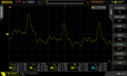
As a side note I measured the output spectrum of ES9018 using 300MHz scope and FFT, it definitely qualifies as RF (see attached FFT) : lots of fur and spikes up to the bandwidth limit of the scope (and surely way above that), MCLK plus its harmonics and subharmonics leaking through, etc, as you'd expect, after all it is a purely digital CMOS chip. The MCLK spike in the output is faster than the scope rise time... However, even if it looks very ugly, the amplitude isn't that large, it is still about 60dB better than a 1-bit DAC...
This might be relevant to topic since someone is probably going to plug an unfiltered voltage mode output ES9018 in your M86 at some point.
Anyway, just sayin' that for audio you actually need some actual lowpass filters ("lowpass" as the RF guys mean it, ie, passive with suitable parts which still works at GHz, not active opamp filter)...
Attachments
As Bruno Putzeys points out, drivers and speakers have energy storage which no test on a linear load will replicate.
The idea is that resistive loads are easy for the amp because AB switching occurs at low currents.
Suppose we drive a resistive load with a sinewave. As the current passes through the crossover region, for small current the OPTs will be both ON, then for larger current one of the OPTs will be OFF, this is classic class-AB.
Even if there is no switching, either because the test signal is small enough or the amp is class-A or non-switching AB, output impedance (ie, 1/Gm) will vary depending on current.
This impedance variation produces a voltage error, which is proportional to DeltaZOut * current.
Whatever the load is (resistive, inductive, etc), if current and voltage are not in phase, the crossover artifacts will always happen at current crossover (not voltage) so they may move around but not fundamentally change.
Of course if the load draws a current that can be resonant then a voltage pulse will give you several crossovers for the price of one 😀
The voltage headroom (Vce) on the OPT may be a factor. On a resistive load, crossover happens when both transistors have their Vce at half supply. If the I/V phase is not 0° this will change. How does the crossover looks when it occurs at an output voltage that is close to the rails ?
You can characterize your output stage and measure all that stuff quite simply. What is needed is Output Z (1/Gm) versus current versus output voltage, a kind of 3D wing diagram. You can also add "versus time and self heating".
One could ground the amplifier input, force a current in the output, and check the output impedance linearity. But you need a current source with much more linearity than the amplifier, which is annoying.
It is much simpler to test the amplifier in a ridiculously low load (like 0.1 ohm), of course with low signal levels, just enough voltage to make the amp output the current you want to test, and minding about output transistors SOA etc. This gives you Z vs current at Vout=0.
Now add a huge capacitor in series with the load resistor, and step the DC voltage on the input signal (slowly). You get your Z vs current vs output voltage. So if something starts misbehaving close to the supply rails it will be immediately apparent.
This is an example of useful, not so usual test signal (plus you can do it with a soundcard and cheap accessories, a cap and a resistor).
Could you provide some detail?One test I do involves a dirty great iron cored choke with a series resistor to make the real part of the impedance up to the amp's minimum rated impedance, as the DCR of a voice coil would do. I do a frequency sweep with this over the bass and midrange, so the output stage gets hit with a variety of impedance magnitudes and phase angles, including the worst case one of 1.4x the minimum at 45 degrees.
I guess I could improve it some more by adding a huge capacitor to form a series resonant circuit that would test the leading phase angles. But even the inductive load showed up some issues with parasitic oscillations that weren't present on a resistive load. It also validates the protection circuits and allows you to check that they won't trigger for reasonable loads (and will trigger safely for unreasonable ones, as you make the resistor smaller)
This is not rocket science and I would like to think it was done with the Modulus-86 too.
Like what values of L & R for a 4ohm rated amplifier (and for an 8ohm, just for me).
And what signals at whatever level?
And what to look for as OK, or not OK?
Could you explain........... I measured the output spectrum of ES9018 using 300MHz scope and FFT, it definitely qualifies as RF (see attached FFT) : lots of fur and spikes up to the bandwidth limit of the scope (and surely way above that), MCLK plus its harmonics and subharmonics leaking through, etc, as you'd expect, after all it is a purely digital CMOS chip. The MCLK spike in the output is faster than the scope rise time... However, even if it looks very ugly,...................
Anyway, just sayin' that for audio you actually need some actual lowpass filters ("lowpass" as the RF guys mean it, ie, passive with suitable parts which still works at GHz, not active opamp filter)...
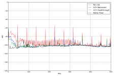
X2Y Balanced, X2Y Feedthrough?
Yeah, when I was handing off composite amplifier design collateral to Tom at the start of the Modulus-86 project we had quite a bit of discussion about ground distinctions, layout parasitics, loop intercepts, and so on. All the core concepts are captured in DIY Audio's grounding article plus if one happens to have a good background in precision analog, power supply characterization, and layout they're not super hard to arrive at independently.
AD used to do a great lecture for universities back in the 80s talking about grounding. First page said in large letters 'Ground: The place where all good signals go to die', then went on to explain all the tricks to actually get the performance you were expecting. All the stuff for precision analog design was known 40 years ago, and yet rarely applied in audio, even when the sales price is up there with good test equipment. It's rare to get a 4 layer+ board in commercial audio, even with mixed signal stuff.
I have not done anything 'precision' since uni so to get within 20dB of what Tom has done would take years, which is why I am grateful for this.
Now where is the matching pre-amp 😛
...
Anyway, just sayin' that for audio you actually need some actual lowpass filters ("lowpass" as the RF guys mean it, ie, passive with suitable parts which still works at GHz, not active opamp filter)...
The Mod86 uses something like the THAT1200 EMI passives as indicated in the datasheet:

"Figure 11 shows a more elaborate and robust circuit for RFI protection.
While more complex, it offers many improvements over the circuit of Figure 10 that make it worth serious consideration. First, C1 and C2 are larger than their counterparts in Figure 10. Because they are in series with each other, they act as a 235 pf capacitor across pins 2 and 3 of the XLR. This allows them to be effective at lower frequencies.
Second, because their center point ties to chassis ground through a smaller, common capacitor (C3, 100 pf), any mismatch in their values has less tendency to unbalance common-mode signals compared to the circuit of figure 104. Third, because they are driven from the common-mode bootstrap circuit through R3, this common point gains the benefit of the InGenius common-mode bootstrapping.
Finally, R1 and R2 provide some additional buildout impedance against which the bypass capacitors can work, making the entire network more effective against strong RF signals."
www.thatcorp.com/datashts/THAT_1200-Series_Datasheet.pdf

😉
Could you provide some detail?
Like what values of L & R for a 4ohm rated amplifier (and for an 8ohm, just for me).
And what signals at whatever level?
And what to look for as OK, or not OK?
The last time I did this, I used an iron cored inductor of about 1mH wound with heavy 2.5 sq mm wire, on a large transformer core with an air gap, and a 4 ohm series resistor, as the inductor had negligible DCR.
1mH has a reactance of 4 ohms at about 700Hz, so the maximum stress on the output stage will occur at about this frequency. I used a sinewave test signal at full power, and swept it over about 2 octaves centred on 700Hz.
You are looking for the amp to maintain a clean output with low distortion into the inductive load. You can do this test with a THD analyser, but be aware that you won't get an accurate distortion measurement if an iron-cored inductor is involved. The nonlinearity of the iron core will interact with the amp's finite output impedance and make the distortion look worse. Maybe you could use a big air-cored inductor from a speaker crossover.
In my case, the test provoked parasitics that were obvious on a scope with no need for THD analysis.
This test is really the dual of the capacitive load one that uses 8 ohms in parallel with 0.1uF or whatever. You should probably do both, and use a bigger capacitor so you can get a 45 degree phase lead within the audio band.
PS: I really ought to go back and add those RF filter networks to the XLR inputs on my last build. 🙂
Last edited:
Could you explain
X2Y Balanced, X2Y Feedthrough?
It is a X2Y C0G capacitor specced at 1nF. These contain two 1nF caps actually, which are well matched. It has 2 GND electrodes (G1 G2, internally shorted) and each capacitor has its own pin (A,B). So if you want to filter a balanced signal you can place it like this :
GSM RFI Suppression with X2Y® EMI Filters
This is the "balanced" label in the plot I posted. It has excellent CMRR because of the good matching between the two internal caps.
The "feedthrough" mode uses one X2Y component with both internal caps in parallel, across the signal line. You use this mode for decoupling also.
Note the measurement is single-ended.
Anyway. In feedthrough/decoupling mode, when properly mounted this thing has low ESL, about 100-150 pH, due to the internal structure which cancels magnetic flux (it is pretty clever). So it makes a pretty good decoupling cap, or filter, if you got one line to filter only. It is about 10x better than properly mounted MLCC capacitors (which themselves are, by the way, about 10x better than the traditional red WIMA plastic inductors which have some capacitive properties at low frequencies)...
In balanced mode, with two signal lines, it is a bit different... For common mode noise it behaves just like the decoupling mode above, that means it is extremely good, with its very low ESL. For differential noise it behaves like a normal capacitor, because the internal flux-canceling structure no longer works (it depends on the current in the two internal caps flowing in opposite directions).
As far as sticking ceramic caps in the audio path, well, it is C0G. Anyone who can manage to measure some THD on this thing needs to clean solder flux better and measure again.
There's an extensive literature you can consult about hanging trafos and caps and whatnot off basic driver equivalent circuits (cap for electrostat, resistor for magnetostat, L+R+(R||L||C) for dynamic drivers) to approximate speaker compliance volumes and such. It's all based on LTI components and hence can't easily model the energy storage associated with back wave time of flight and such within the speaker enclosure. In principle, an RLCG delay line can get the delay. In practice, tens of thousands of components are required, making it infeasible to build on the bench and difficult to get convergence on in Spice. Delayed sources or equivalent constructs like transmission lines work are much more simulator friendly, though still problematic on the bench. For example, if you want an electrical approximation of the about 1.5ms round trip propagation delay in a floorstander a delay line around 200m long is needed.I guess I could improve it some more
Result is commonly used models fail to align with subjective findings as they show nearly no difference between, say, monoamping, biwiring, passive biamping, and active biamping. LTSpice is nice for working with delays. On the bench it's easiest just to measure a real speaker.
Careful with that. The 2Y matching of 2-3% is tighter than X2Y caps' 20% rating but in no X2Y datasheet I've looked at has it been a specified parameter, meaning it's not guaranteed. It's also not anything special. At least with the distributors I use two 1% C0Gs cost less than one X2Y. So, unless board space is really limited, one might as well go with the 40dB CMRR typ 1% caps offer. Compared to the 85 to 100dB that's routine for difference amplifiers 40dB is pretty poor. It means the cap mismatch will start to degrade CMRR two or three decades below the filter's corner frequency. So if one corners an EMI filter at a few hundred kHz one has to pay attention to avoid CMRR degradation around 1kHz.It has excellent CMRR because of the good matching between the two internal caps.
THAT's EMI network is pretty elegant about mitigating this by kind of floating the 2Y so it behaves more like an X and taking advantage of the bootstrap servo. Johansen's marketing doesn't document their test configuration well but it wouldn't surprise me if the 10x improvement claimed is relative to 20% MLCCs. If so, it's both specious with regards to component tolerances (I often see 5% MLCCs coming up cheapest in the parts selector) and wanting some care when being applied to audio circuits where some flexibility exists as to how the connection to "ground" is made.
Your aside about RC lowpass being required on DAC output pins to minimize GBP burn or TID/SID on DEM transients in the output buffer is bang on. If one's trying for low output offset X2Y balance and CMRR in these circuits isn't trivial either.
Yeah, integral windup matters, either in the narrow PID sense or the more general sense of error accumulation as the control loop opens. It's not necessarily related to railing or clipping. Thermal protections like National's SPiKe can potentially trip anywhere in the swing---about half max power is most likely as that's where maximum dissipation occurs.So if something starts misbehaving close to the supply rails it will be immediately apparent.
Most any 32+bit DSP and pro audio interface will do fine. I use Reaper with a few different bits of Focusrite hardware. One can DIY a better DAC but the unambiguous part of the improvement is about 0.3 gnat farts.Now where is the matching pre-amp
Most any 32+bit DSP and pro audio interface will do fine. I use Reaper with a few different bits of Focusrite hardware. One can DIY a better DAC but the unambiguous part of the improvement is about 0.3 gnat farts.
Sadly my usecases don't allow that as have 4 digital and 3 analogue sources hooked up. One day I will wake up and accept that A/D can be more transparent than my ability to detect and parts of my audio life will get easier 🙂
In practice, tens of thousands of components are required, making it infeasible to build on the bench and difficult to get convergence on in Spice.
This reminds me of another engineering joke. (Yes, there is more than one.) A mathematician and an engineer are in a bar of somewhat ill repute. A beautiful woman appears, takes off all her clothes and announces that each 10 seconds she will halve the distance between herself and our protagonists.
"That's terrible" says the mathematician, "She will never get here!"
To which the engineer replies, "Soon she'll be close enough"
We are not interested in modelling a speaker exactly, we are interested in modelling the effect that speaker impedance can have on an amplifier, and that basically boils down to impedances with phase angles other than zero. I argue that the exact details don't matter as long as the load is heavy enough and reactive enough.
My recommendation of a resistance equal to the amp's minimum load, in series with a reactance of the same value at the test frequency, is something of a worst case. Maybe a really sadistic speaker designer could come up with worse...
Maybe a really sadistic speaker designer could come up with worse...
I like ribbon speakers. Luckily mine are an easy load, but early apogees were known to engage in death matches with the amplifers connected to them. Which of course begat the fashion for class A amps that could drive nails happily 🙂
Real-Life Measurements | Stereophile.com details the simulated speaker load that stereophile use. Whilst more of marketing use than anything else, measuring against this would at least allow the curious to compare against the considerable database of measurements online, but at least this simulates a real speaker.
Which leads into the next question. Some have experimented with 4 wire kelvin sensing connections to speakers over the years. When we get to the level of performance we have here is there any dBGnatfart extra to be gained? I suspect not...
I've heard this referred to as the "Unfair to Amps Club". 🙂 As this is the DIY world, if you happened to get a pair of early Apogees then you could measure the actual minimum impedance found anywhere in the frequency range, and design an amp just for them. It might end up with +/-15V rails at 25 amps each and output transistors from a welding machine (and certainly not a LM3886) but I argue that you could still test it with my method (or the Stereophile test load) by scaling the impedance of the test load.
Mmm, the point I was trying to make is some of us have already gone there and found the approach insufficient to capture subjectively interesting behavior that's nontrivial. Have fun and look into what guitarists call tone suck sometime.we are interested in modelling the effect that speaker impedance can have on an amplifier
It depends. 😉 So, long answer.When we get to the level of performance we have here is there any dBGnatfart extra to be gained?
Usually the argument runs error created by local power amplifier sense must be negligible as the cable and connector impedance is much lower than the speaker/driver impedance. There tend to be two problems with this line of reasoning. One is it's usually applied within LTI models (such as what scopeboy is pursing). These are able to capture things like SPL changes around bass resonance in drivers as amplifiers convert over to current source behavior. So they certainly work for what one might call gross phenomena. But, within the relatively small range covered by typical amplifier+cable voltage source impedances, the models indicate the ratio between source and load impedances should have negligible effect on the output. So they're insufficient to explain subjective experiences like the desirability of periodically retightening binding posts.
The other difficulty is the limit of audibility is usually 50 or 60dB down, meaning if the load impedance is ohms then the cable impedance needs to be milliohms to render sense error inaudible. Most cables don't meet this criteria, particularly above 1kHz or so where inductance starts to contribute meaningfully to their impedance (if one has a look in an electromagnetic field solver skin effect works out to be insignificant in most cable geometries---I know, I know, I'm crazy people). So the reasoning falls apart internally as it's based on asserting something that's significant by its own criteria is insignficant.
When models break down like this the question becomes what factors are they not taking into account. The simplest answer with speakers seems to be the enclosure doesn't have an infinite return loss, meaning that even with an otherwise ideal enclosure (no panel resonances or such) some of the stored wave energy I've been mentioning about returns to the drivers and reradiates out the front of the cones as an error term. It's easy to establish bounds on the resulting damping factor requirements. In a typical box the worst return losses are 20dB or less, meaning DF needs to exceed 100 to hit a 60dB down definition of inaudibility. Optimized enclosures should be less sensitive in this regard. For example, a well tuned Linkwitz Pluto manages 40dB so it'd only need a DF of 10. A DF of 10 isn't hard. A DF of 100 is not exactly trivial even at a couple hundred Hz. AWG 12 is 5 milliohms/meter, meaning a typical two meter zip run consumes 20 milliohms of the 30 milliohm or source impedance budget needed to obtain a DF of 100 on 4 ohm nominal speaker with some dips. SpeakON contact resistances are 2 milliohms, meaning you're at 28 milliohms after plugging in both ends of the cable. Add something for inside the chassis and inside the speaker and, well, DF 100 is not happening without some careful attention.
I like this line of reasoning as it yields AB testable hypotheses on the audibility of cable and other source impedance changes. I lack the ability to conduct fully proper DBLTs on this, but I approximate the best I can with a mono mix on two drivers or speakers set right next to each other and blindly toggling channel enables until I've no idea what's active. The findings are pretty much what one would expect; placing amps next to box speakers with short cables is subjectively preferable to farther away with longer cables, a larger reduction in source impedance from changing out a longer wiring run internal to the speaker makes more of a difference than a smaller change on a shorter external run, using low inductance cables on tweeters has more of an effect than reducing inductance on feeds to woofers of comparable impedance, and so on. I've also shown I can't discriminate between a meter of AWG 12 zip and a number of lower impedance cable runs on dipoles---where the "enclosure" return loss is about as close to infinity as you're going to get---whereas I can discriminate among the same cable runs with the same amps connected to a box speaker (drivers had the same size QCs; handy that).
Based on all this I would say there's 0 dBGF to be gained from remote sense in power amps. What makes remote sense interesting is the potential to alleviate cable and connector requirements, particularly in typical box speakers. This is mostly a hi-fi thing. In pro audio it's routine to have amp channels and active XO+EQ integrated into the speaker already. The whole hi-fi thing of separate amps, managing transitions through amp and speaker binding posts, and passive XOs is pretty awkward in comparison. One can band-aid this with remote sense by rejiggering all the connectors and stuff. But, really, it's easier to address the underlying problems as much as one can and then throw copper at the remainder. Also saves worrying about keeping noise ingress in the remote sense low enough there's net reduction of error compared to local sense.
That said, remote sense is technologically cool and, as an amp designer, something I've looked into. I'd not, however, put it into a production amplifier like the Mod that's intended for general use.
Last edited:
Mmm, the point I was trying to make is some of us have already gone there and found the approach insufficient to capture subjectively interesting behavior that's nontrivial. Have fun and look into what guitarists call tone suck sometime.
I've been playing electric guitar for 20 years and have built a half dozen guitar amps. (Some of them sounded really bad but that is another story 🙂 ) I believe "tone suck" refers to loss of high end caused by the guitar pickups being loaded down by the capacitance of an overlong guitar cord or multiple effects pedals.
I can't see how this has anything to do with power amp design or amp-speaker interaction. Speaker cable capacitance is negligible, and the output impedance of a decent solid-state amp is low enough that capacitive loading will destroy the output stage before it drags the HF response down.
I still don't see anything going on that needs 10,000 Spice components to model. 10, maybe.
Last edited:
AD used to do a great lecture for universities back in the 80s talking about grounding. First page said in large letters 'Ground: The place where all good signals go to die', then went on to explain all the tricks to actually get the performance you were expecting.
The irony is that many engineers put tons of care into getting the VCC routed correctly but get laissez-faire with the ground. This is especially the case when it comes to decoupling capacitors.
It's rare to get a 4 layer+ board in commercial audio, even with mixed signal stuff.
I'm pretty content with two layers at this time. Sometimes a third layer would be nice.
Now where is the matching pre-amp 😛
Patience, Grasshopper... I happen to be absolutely AWESOME at starting projects, so I have been kicking around the idea of a preamp. Right now it's most definitely in the idea stage and I have a couple of projects ahead of it that I need to complete first, but at some point, there will be a matching preamp.
Figure 11 shows a more elaborate and robust circuit for RFI protection.
THAT1200 Figure 11 is what you want for EMI protection. You can then expand further and include ESD protection as well, as I did on the MOD86.
~Tom
Fair point; I was using the term in the power brake sense.I believe "tone suck" refers to loss of high end caused by the guitar pickups being loaded down by the capacitance of an overlong guitar cord or multiple effects pedals.
So, which 10 components get you a 1.5ms propagation delay without use of a transmission line or delayed source?I still don't see anything going on that needs 10,000 Spice components to model. 10, maybe.
- Home
- Vendor's Bazaar
- Modulus-86: Composite amplifier achieving <0.0004 % THD+N.