Does his SMPS have enough output capacitors to be connected directly to Modulus86 board or it is recommended to have bulky reservoir capacitors (like your Power86 module) between SMPS and Modulus86 (or LM3886DR, as it has similar PS scheme).Two LOP-300-30 would be perfect for a Modulus-86 amp. $89 for a pair of them at Mouser versus $118/each for the Connex (including "express" shipping, and assuming you buy two of them like I did a month ago).
Yep. Plenty. In fact, as long as the power supply has sufficiently low output impedance, all the capacitance you really need is on the Modulus-86 board itself.
The regulated power supplies, such as the LOP series, tend to have very low output impedance, i.e., the output voltage hardly varies as the load current varies.
Tom
The regulated power supplies, such as the LOP series, tend to have very low output impedance, i.e., the output voltage hardly varies as the load current varies.
Tom

Looking at your feedback resistor measurements with interest.
Maybe for the fun of it, measure a resistor both ways? Possibly with phase? 🙂
Reluctantly I found a difference mounting them low impedance node to high impedance node or the other way around. But I cannot measure anything noteworthy with my limited equipment.
Tom, are wirewound resistors suitable for a feedback network? As far as I know these are µH inductors (if not specially wound). At 20 kΩ the resistive part surely is dominant, but does it extend well in frequency? I suppose a 1 kΩ resistor does peak in the impedance graph?
Possibly with phase? I don't know what you mean.Maybe for the fun of it, measure a resistor both ways? Possibly with phase?
Not really. They can result in instability due to their inductance. But there are non-inductive (or low-inductive) types out there. I'm not sure I'd use those either, but it was cheap to try.are wirewound resistors suitable for a feedback network?
Tom
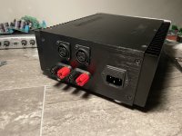
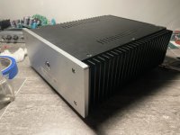
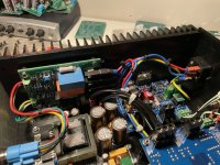
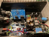
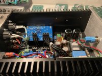
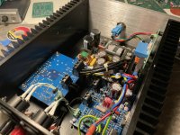
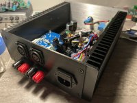
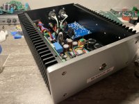
Finally finished my Modulus 86 build! I was able to fit it all in a nice compact case.
Added board that switches power on/off using NE555 and relay.
Input buffers are OPA1656 - I like how they sound.
Overall very detailed amp and most important for me - it sounds “musical”!!! while THD is 0.0002 or so!
Added board that switches power on/off using NE555 and relay.
Input buffers are OPA1656 - I like how they sound.
Overall very detailed amp and most important for me - it sounds “musical”!!! while THD is 0.0002 or so!
Attachments
-
 IMG_3280.jpeg459.6 KB · Views: 238
 -
 IMG_3289.jpeg447 KB · Views: 240
 -
 IMG_3288.jpeg370.4 KB · Views: 210
 -
 IMG_3287.jpeg384.6 KB · Views: 225
 -
 IMG_3286.jpeg522.6 KB · Views: 234
 -
 IMG_3285.jpeg583.5 KB · Views: 242
 -
 IMG_3284.jpeg476.6 KB · Views: 247
 -
 IMG_3283.jpeg555.1 KB · Views: 254
 -
 IMG_3282.jpeg410.9 KB · Views: 231
 -
 IMG_3281.jpeg463.4 KB · Views: 236
Please help me reviewing this PS board I designed for a single channel modulus-86.
A little explanation:
1. this should fit in a very tight space, that's why I used horizontal capacitors
2. I would like to use my active rectifiers that do not support center tapped operation, so I need a separate rectifier for both rails.
3. There is a separate little power supply for a fan on the top.
One thing I am pretty sure is missing is a chassis ground connection. I would love to get suggestions on where to place it.
Thanks in advance.
torzsok
I suggest keeping the AC inputs together to minimize the amount of wiring to the secondary of the transformer.
I'd also use thermal reliefs rather than solid connections to the pours if you want any hope of being able to solder the components to the board.
Tom
I'd also use thermal reliefs rather than solid connections to the pours if you want any hope of being able to solder the components to the board.
Tom
Thanks, Tom. I thought that a pair of twisted wires above the board is better than two longish parallel traces on the board, but that would be an easy fix.
How about the chassis ground connection?
Is it ok, that the fan supply is not connected to any ground?
How about the chassis ground connection?
Is it ok, that the fan supply is not connected to any ground?
If you rotate C1 and C2 90º clockwise and move them to the left edge of the board you could put both rectifiers on the right along with their AC connections. Then either take the DC output along the left edge of the board or over by the AC input. That's probably the smallest loop area you'll find -> lowest coupling to the external world.
My thinking is this: The secondary current in the transformer is a spiky pulse train. That'll love to couple into stuff, so you really want to minimize the wiring to the transformer and keep it tightly coupled. The loop area from the rectifier to the caps is nice and tight due to the use of pours, but the input wiring could be tighter. I'd move the traces closer together. Even if you etch the board in your garage, you should have no trouble getting 15-mil (0.4 mm) spacing.
I'd follow AES48-2019 for the chassis grounding.
The fan supply can float. The fan doesn't care where ground is.
Tom
Thanks, Tom. Due to the tight and unusual space this thing needs to fit in, I don't want to change the orientation. I came up with this instead, trying to follow you. I placed the chassis ground connection between the ACs.

I'm thinking you'll want larger footprints for the two 5k6 resistors. They'll be power types.
I'd play with the rotation of D1 and D2. I bet if you rotate them 90º you can make an even tighter layout as the distance (and, thus, loop area) to the caps will be reduced.
I would add four mounting holes large enough to feed a wire tie through so you can tie the top ends of the caps to the PCB.
You'll probably find that a leaded/PTH cap for C3 will be smaller than the SMD one used now. D4 could be a WOG type (leaded/PTH).
Where's D3? If no D3, re-annotate the board.
I know I said to reduce spacing on the AC lines. Just make sure that you don't run them at minimum space. If your manufacturer supports, say, 5-mil spacing run the lines at 8-10 mil spacing. Never push the process unless you have to.
Tom
True, noted, corrected. Thanks.I'm thinking you'll want larger footprints for the two 5k6 resistors. They'll be power types.
This is what I can not do unfortunately. I will try to fit this is a tube, and my rectifier pcbs are too tall for thatI'd play with the rotation of D1 and D2. I bet if you rotate them 90º you can make an even tighter layout as the distance (and, thus, loop area) to the caps will be reduced.
Great idea!I would add four mounting holes large enough to feed a wire tie through so you can tie the top ends of the caps to the PCB.
I felt so good about doing it mostly SMD. I can live with a PTH solution too.You'll probably find that a leaded/PTH cap for C3 will be smaller than the SMD one used now. D4 could be a WOG type (leaded/PTH).
Done.Where's D3? If no D3, re-annotate the board.
I checked the manufacturer, they support 150um, which is less than 6 mil. The default setting was 7.87mil, I think I will go with it.I know I said to reduce spacing on the AC lines. Just make sure that you don't run them at minimum space. If your manufacturer supports, say, 5-mil spacing run the lines at 8-10 mil spacing. Never push the process unless you have to.
I like that, thanks! Here is a version with all the suggestions that I could incorporate:I'm thinking you could move the bridges apart, rotate that connector and put it in between the bridges - that would make for shorter traces.
I've been using RCA input on my Modulus 86 but now have a source with fully balanced output. Will there be a sonic change/improvement if I change the RCA to XLR input and use balanced signal even if cables are 1 m long?
I've always preferred balanced connections. Even short ones.
Many moons ago a friend of mine and I compared balanced vs unbalanced on a Parasound P3 and A23 amp. We both expected there to be no difference going into the experiment and we both preferred the sound with the balanced connections. Of course, this was a completely uncontrolled experiment - or experiments (we both played around with the stereo on our own in two different settings) - but the conclusion was clear. The differential connection sounded better. It wasn't an overwhelming difference but worth taking.
On the Modulus-86 the balanced input is basically free - or included in the cost of admission. So use it! Should you later decide that you want to switch back to single-ended connections, you can always use an adapter like the Neutrik NA2MPMF.

Tom
Many moons ago a friend of mine and I compared balanced vs unbalanced on a Parasound P3 and A23 amp. We both expected there to be no difference going into the experiment and we both preferred the sound with the balanced connections. Of course, this was a completely uncontrolled experiment - or experiments (we both played around with the stereo on our own in two different settings) - but the conclusion was clear. The differential connection sounded better. It wasn't an overwhelming difference but worth taking.
On the Modulus-86 the balanced input is basically free - or included in the cost of admission. So use it! Should you later decide that you want to switch back to single-ended connections, you can always use an adapter like the Neutrik NA2MPMF.
Tom
I'm putting together a build plan for a stereo amplifier. My thinking is to keep the cost down by having a cooling fan which would reduce the heat sink size and therefore also the total cost.
As for the power supply a Meanwell LOP-300 30V looks really economical. According to the LOP-300 data sheet it can produce 300W continuous with a 10.98CFN FAN and 180W without. It also has a built in 12V/0.5A rail for an external fan which is very convenient. Any reason a LOP-300 with a fan wouldn't be able to power 2x Modulus-86?
Between a LOP-300 and 300REh (EUR 99) the LOP-300 (EUR ~44) seems like a no brainer at less than half the price. A random fan I googled - ARCTIC P12 Max 120mm has 80cfm and costs EUR ~7, that brings the total to EUR 51. The fan has a 4 pin connector, but I guess with ground and DC+ at certain voltage while leaving the control and sense pin unconnected it would still work at a desired speed.
What the LOP-300 does not have as opposed to the 300REh is an inrush current limiter.
My Logitech Z2300 2.1 speaker set is rated 200W continuous and 480W peak and has a slow-blow fuse rated 2A. 2A * 220 VAC = 440W. So I guess the fuse can take 480W for a bit.
A LOP-300 with a fan can do 300W continuous and peak 450W for 3 sec. according to it's data sheet. Looks to me like a 2A (or there abouts) slow-blow fuse would be suitable if there is a soft-start circuit that limits the inrush current to less than 2A @ 220VAC.
This is where things get fuzzy for me. I looked up soft-start boards and found some on Ebay and Audiophonics, but nether state what the inrush current is limited to.
Here are 2 of the cheapest on Audiophonics (EUR 15 and 22):
https://www.audiophonics.fr/en/soft...rt-module-230v-15a-for-amplifiers-p-4415.html
https://www.audiophonics.fr/en/soft...r-control-and-delay-for-amplifier-p-4155.html
How does one know what the inrush current is limited to? Is ether of these suitable for use with a 2A safety fuse? Seems to me like the first is not, but I don't understand the whole of the circuit.
Let's say that the 2nd is suitable, then it + LOP-300 + above mentioned 7 EUR fan comes to a total of EUR 73 which is still less than 99 EUR for the 300REh power supply. The fan helps further reduce total amp. cost if it also blows air on the chip amp heat sinks.
A curious thing that I see in the LOP-300 data sheet is that it says "3 max" at the left bottom corner (see page 5). But "3 max" of what? From the installation manual: "At least 5mm insulation distance on the bottom of the unit should be kept and a Mylar film should be added between the unit and the system." So, it can't be a maximum of 3mm space below it. Doesn't really make sense to mount the board with a maximum of 3 spacers ether does it? Is it the maximum extrusion length of the feet of electrical components on the board according to manufacturing specifications?
And what is that plastic screw terminal in the right corner of the schematic below 2 caps for?
Then there is also the Mylar film. Is it necessary to have one below the LOP-300 glued to amp chassis or can one do without one if there is nothing but the amplifier chassis floor below it?
Data sheet and installation manual from Meanwell:
LOP-300: https://www.meanwell.com/webapp/product/search.aspx?prod=LOP-300
PCB Installation manual: https://www.meanwell.com/Upload/PDF/PCB_EN.pdf
Last edited:
- Home
- Amplifiers
- Chip Amps
- Modulus-86 build thread