215 is below range. You should have addressed your concern to National Grid or your local distribution company.
Do you know how low that went when you were not looking/measuring?
Did you see my posts about my local co.
They responded the same day and had a monitor on the phases within the week.
They did take a long time to finally sort the problem, but other than that slow change of equipment, their attitude to alleged out of range report was exemplary.
215 is below range. You should have addressed your concern to National Grid or your local distribution company.
Do you know how low that went when you were not looking/measuring?
Yeah I complained in 2004. They monitored me and agreed it was low. We also had very regular nuisance trips (overhead lines). They promised to uprate things. By 2009 when I got divorced nothing had been done. Gotta love SSE.
Here is the schematic of the simulation.
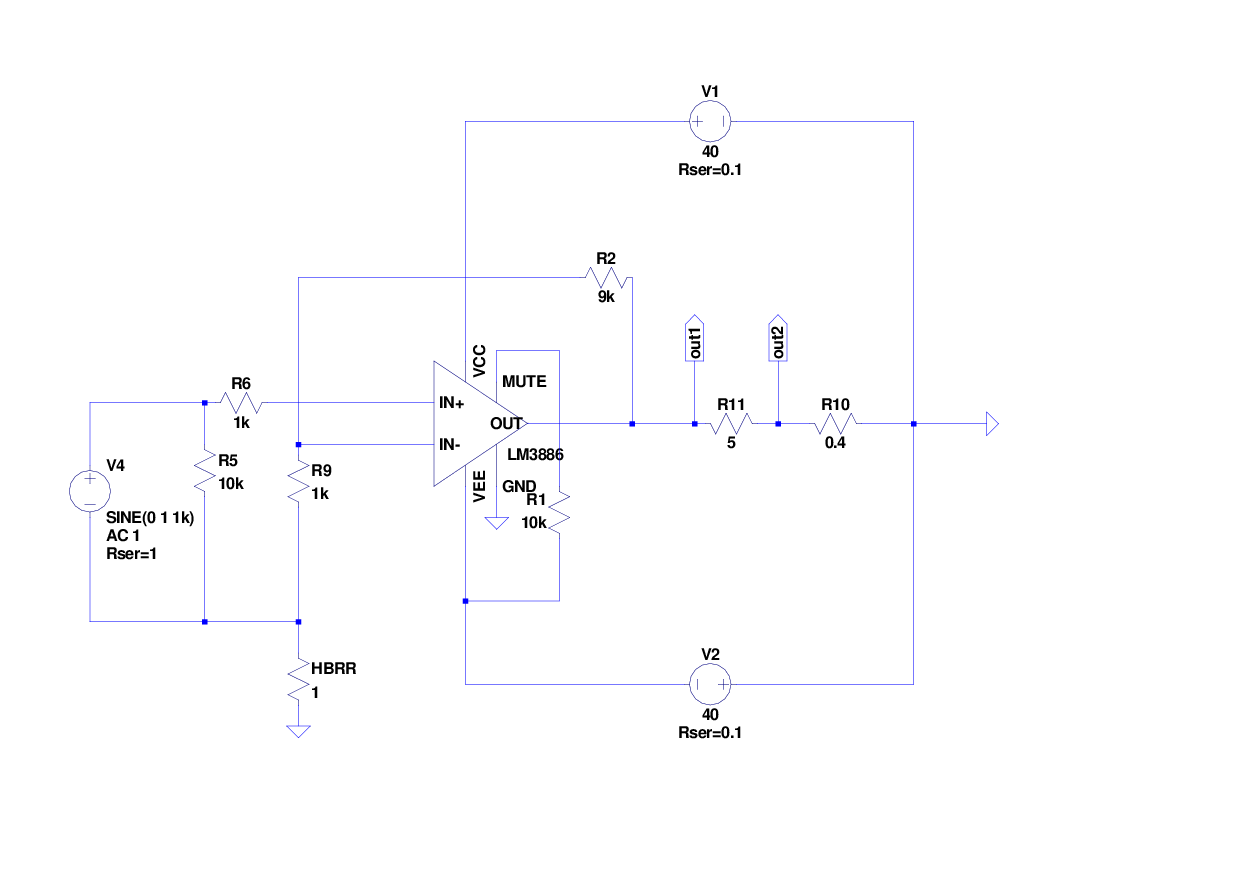
Mark, I checked as best I could, and the added cap does seem to fix it. . . when comparing while utilizing a badly made switchmode powered music source at input. Every computer at the Wal-Mart and for sure, also that Dell factory, would probably qualify as such a source, in which case, you'll want to add that cap. 😀If R2 refers to large signal, then so must R9, otherwise a little error results. However, that trouble is high pitched, so a possible fix is a little cap in parallel with HBRR.
Also, I've heard an amp made like that schematic and I really tried to describe how I feel about that, but that didn't work. I was trying to decide if it was a buffer that failed, an astonishingly effective burglar alarm or the latest in upmarket high efficiency space heaters, but couldn't determine which it was. At this point, how would I know if adding the little cap would help it?
Today, we have more resources--please use Philfr's schematic to do proofing with simplified LM3886 amplifiers. That's because, I think it would be pleasant and simpler to use examples that work practically, prior to proofing concepts on them. A simulator alone doesn't quite get it. I was so distracted!
Adding a capacitor will have (almost) no effect. Ignore R10 and the low gain (R2) and you have the datasheet version plus ground loop control.
Indeed that is true of that schematic.Adding a capacitor will have (almost) no effect. Ignore R10 and the low gain (R2) and you have the datasheet version plus ground loop control.
However, I can't use that schematic.
So, there could be apples with oranges when trying this.
Hi Domi
I'm considering the slightly bigger version of this case. However I notice that the sides are not proper heatsinks. Do you find they dissipate the heat OK?
Thanks
Ian
Hi Domi
I'm considering the slightly bigger version of this case. However I notice that the sides are not proper heatsinks. Do you find they dissipate the heat OK?
Thanks
Ian
Ok now seen your post about this. As you have such efficient speakers I doubt I can draw any conclusions from your experience.
Mark, I sincerely apologize for some of my comments. The source of that error was my short capacity for viewing a schematic that I couldn't quite deal with, and for sure, had we used it, the LM3886 might have said a few things worse than I did. Apparently, I lack for imagination so far as the capacity to overlook the rather unhappy chip and instead look at what you were talking about, which was quite different, reasonable, interesting and valuable.. It was kind of like an LED flashlight at point blank range, a little hard to see around that, and I reacted unsuitably. Still sorry about that.Adding a capacitor will have (almost) no effect. Ignore R10 and the low gain (R2) and you have the datasheet version plus ground loop control.
Your schematic would probably work well if the inputs were flipped to achieve inverting mode. But, otherwise, please use Philfr's schematic on the grounds that it is easier to mod something that is already in active service because it works well. After that point there's more opportunity to study alternations more comfortably.
Tom had a little different take on this--he added some RC so that the LM3886 would remain calm, even at low gain and pushed rather close to the rails. Inverting mode would make that job easier, and Philfr's schematic is higher gain along with carefully chosen values that happen to work. Tom's added RC's onto Philfr's amp results in getting the LM3886 up to a highly suitable performance. And, well, I think that is amazing.
It is when an amplifier is quite healthy and working well that it can be used as measuring equipment, which then has the effect of facilitating measuring (by widely various means) by a much broader audience. It is in that case where I probably could manage a helpful comment. See? That function is so much better than that earlier business; and, I do apologize for that.
P.S.
If that was too wordy: Mark's schematic dealt with options at the input circuit and wasn't specific to the LM3886 itself, but rather a low gain tolerant small signal op-amp could be used as demonstrator. Anyway, it was a concept schematic and it did work for that.
Last edited:
Can I just check something. To make sure the chip is screwed to the heat sink in right position for the pins to be able to properly go through the pcb, is the idea that you set the jig up as Richidoo describes, then slide the chip pins through the pcb and then screw the chip to the heat sink with the chip in stu ( but unsoldered) ?A bit of an issue I noticed during assembly, hopefully this will help others avoid a problem...
When the chip is placed vertically in the PCB holes, gravity pulls it down and causes it to "slouch" a little, making the bottom edge of the chip duck inside the edge of the PCB and away from the heatsink mounting plane. If you solder it like this it will not contact the heatsink properly and enter protection and sound bad!
When the chip is "slouched," the interference of the PCB past the chip's rear surface plane is about 0.015", or maybe .25mm, just guessing by eye.
When possible, it is best practice to mount power transistors to their heatsink before soldering to the PCB and if this is done the chip is held in the right orientation, cannot slouch, and you will have no interference from the PCB when you do the final mounting. Since this chip requires no insulation from heatsink, so there is no insulation thickness to consider, you can mount it to the heatsink dry for the soldering. If you use a metal backed chip then use the insulation when soldering.
To illustrate the issue: If you place the chip on its back on a flat surface, then slide it into the (vertical PCB) holes the chip stays flat up until the very last smidgeon of insertion, then the back of the chip lifts off the surface when the pins are all the way home. So when the chip is placed vertically into the horizontal PCB, gravity pulls it all the way down and creates the slouch, pulling the chip away from the heatsink plane.
Screwing down the chip first (dry) still allows the PCB to easily slip onto the pins. I wouldn't recommend changing the PCB dimensions because that edge actually makes installing the chip in this way easier because the PCB edge holds the PCB at the perfect height for sliding the vertical PCB onto the horizontal screwed down chip pins. It's like somebody knew what they were doing! 😛
With standoffs screwed on the the PCB, use some kind of right angle reference (I used another heatsink standing vertical) to position the PCB perfectly perpendicular to the horizonal heatsink which has the chip attached. Then tack solder some pins from front and back rows, remove the assembly from the jig and fully solder all the pins on the bottom of the PCB.
In the instruction manual, Tom states:
"14. ICs: U2, U5, and U6. When soldering the LM3886 (U2), ensure that U2 can be mounted to a heat sink without stressing the leads on the IC."
So if you do this step you'll find a way to prevent this issue, but if you just merrily "solder everything together" you'll have problems later mounting to the heatsink because the chip has poor posture and likes to slouch. The interference is too small to notice by eye. You want to be able to place the chip in the middle of the heatsink, not on the edge of the heatsink which would be required if the chip was soldered while slouched.
Slight edit: maybe not actually screw it whilst it is in situ but mark the position for the screw / bolt on the heat sink whilst the chip is in situ - ?
Last edited:
Can I just check something. To make sure the chip is screwed to the heat sink in right position for the pins to be able to properly go through the pcb, is the idea that you set the jig up as Richidoo describes, then slide the chip pins through the pcb and then screw the chip to the heat sink with the chip in stu ( but unsoldered) ?
When I built my 4-channel MOD86 amp, I soldered all components except the LM3886 to the board. I then placed the board in the chassis and marked the four mounting hole locations for the board on the bottom of the chassis. I then mounted the board in the chassis and made a mark on the heat sink that lined up with the centre pin of the LM3886 footprint. I then stuck the LM3886 into the footprint and marked on the heat sink the height where I wanted the mounting hole. Disassembled everything and drilled, tapped holes in the heat sink. Then mount the boards, mount the LM3886 to the heat sink, and solder 3-4 pins from the top. Disassemble and solder the rest of the pins from the bottom.
It's a bit laborious and the procedure above sounds far more complicated than it really was. If you're into CNC machining, I'm sure you can get a program going from the measurements I give in the design doc as well as those in the LM3886 data sheet.
Tom
Tom had a little different take on this--he added some RC so that the LM3886 would remain calm, even at low gain and pushed rather close to the rails. Inverting mode would make that job easier, and Philfr's schematic is higher gain along with carefully chosen values that happen to work.
I use a couple of RCs for various reasons. The first RC extends the bandwidth of the LM3886 output stage. It acts as a phase-lead compensation for the global loop. This network would be severely impacted if the LM3886 part of the show was made inverting.
To keep the LM3886 stable near the rails, a compensation cap is needed. That's the Cc you see in the data sheet. I ended up at a slightly lower value than the value given in the data sheet. This capacitor is completely independent of whether the LM3886 is used in inverting or non-inverting configuration.
Tom
Thanks Tom. When you say, "Disassemble and solder the rest of the pins from the bottom."
clearly you have to dismount the pcb from the base of the case to be able to solder from underneath, but did you also disassemble the chip from the heat sink? If so, why?
clearly you have to dismount the pcb from the base of the case to be able to solder from underneath, but did you also disassemble the chip from the heat sink? If so, why?
Thanks Tom. When you say, "Disassemble and solder the rest of the pins from the bottom."
clearly you have to dismount the pcb from the base of the case to be able to solder from underneath, but did you also disassemble the chip from the heat sink? If so, why?
Proximity. If you've got a pin or two tacked on to the 3886, you're golden (it won't move out of alignment). I'd imagine it's darn tough getting your iron in that close to the heatsink. (Never done that!)
Ah right. My boards are in transit so I'm guilty of getting ahead of myself. It's probably obvious when you have the pcb in front of you.
Thanks Tom. When you say, "Disassemble and solder the rest of the pins from the bottom."
clearly you have to dismount the pcb from the base of the case to be able to solder from underneath, but did you also disassemble the chip from the heat sink? If so, why?
Having the LM3886 dangle by a few pins while attached to a heat sink is not a stable arrangement. I prefer to add as little stress on the pins as possible during assembly, so I take the five seconds to undo the screw attaching the LM3886 to the heat sink.
Also, when assembling my first Parallel-86, I learned the hard way that the weight of a 0.4 K/W heat sink will easily bend all the pins of the LM4780 when the whole contraption topples over. See my comment about stability above. 😉
Tom
I've ordered the boards from Tom and the parts from Mouser. Do any of the UK/European builders have advice on suitable transformers available this side of the pond and also enclosures for a standard stereo build?
Thanks, Ian
Thanks, Ian
The usual
RS, Farnell, Rapid,
If any have a special offer, then that could be the cheapest.
I bought some batches of non ROHS
The UK has some very good specialist transformer manufacturers, but their pricing is usually two to three times what RS would charge.
Toroidy if you want an EU product.
RS, Farnell, Rapid,
If any have a special offer, then that could be the cheapest.
I bought some batches of non ROHS
The UK has some very good specialist transformer manufacturers, but their pricing is usually two to three times what RS would charge.
Toroidy if you want an EU product.
Ian
I got my transformer from Avel Lindberg. As for a case, I spent some time looking on eBay but didn't find anything suitable at a reasonable price. I will probably end up buying one from Hi Fi 2000
Ian
I got my transformer from Avel Lindberg. As for a case, I spent some time looking on eBay but didn't find anything suitable at a reasonable price. I will probably end up buying one from Hi Fi 2000
Ian
- Home
- Amplifiers
- Chip Amps
- Modulus-86 build thread