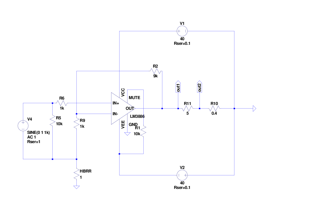
The schematic posted at #978 shows a possible cause of AndrewT's near 0V measurements of HBRR. HBRR and HBRL are parallel, halving the voltage, then there is the connection between source GND and PE, lowering it further.
If R2 refers to large signal, then so must R9, otherwise a little error results. However, that trouble is high pitched, so a possible fix is a little cap in parallel with HBRR.Here is the schematic of the simulation.
Tom,
I too am building a 4 channel Modulus-86 for my LXminis. I have ordered an Antek AS-3222 and only one Power-86. Can I use 22000 caps in the power supply?
Also, what are the output connectors you have used in both of your LXmini builds?
I too am building a 4 channel Modulus-86 for my LXminis. I have ordered an Antek AS-3222 and only one Power-86. Can I use 22000 caps in the power supply?
Also, what are the output connectors you have used in both of your LXmini builds?
I too am building a 4 channel Modulus-86 for my LXminis. I have ordered an Antek AS-3222 and only one Power-86. Can I use 22000 caps in the power supply?
Sure. Bigger is better. As long as the caps can handle the voltage and will fit on the board, you'll be fine.
Also, what are the output connectors you have used in both of your LXmini builds?
I used Neutrik 4-pole SpeakON connectors.
Tom
Well I can sort of announce progress. Thanks to one of the members on this forum who was getting rid of some equipment he no longer needed I now have transformers and no excuse for not getting the amps actually running. Beggars not being able to be chosers this will have me running +/-35V rails give or take (Just measured line voltage. At midnight with nothing on its 253VAC so could be running as high at 38v). This is pushing things beyond the data sheet so will have to be careful with the heasink mounting. But living dangerously is fun 🙂
The LM3886 can take up to ±42 V and a bit higher if it's not driving a signal. The on-board regulators for the op-amps can survive 35 V input-to-output, so they'll be OK as well.
±38 V, unregulated is pushing it beyond my comfort level, but ±38 V under worst case mains conditions is still within spec.
With sine wave testing, 4 Ω load, and worst case dissipation operation, the LM3886 will be pushing the thermal limit. The isolated LM3886TF will be well into thermal shutdown once the heat sink has warmed up. Thankfully, most people don't listen to sine waves and their amps survive just fine. Also, very few people actually run their amps at those power levels.
Go bold or go home! Just keep an eye on the voltage.
Tom
Last edited:
try to get you voltmeter checked.............. At midnight with nothing on its 253VAC.........
253Vac is the top limit for UK mains, other than for very short term overvoltage moments.
try to get you voltmeter checked.
253Vac is the top limit for UK mains, other than for very short term overvoltage moments.
Yeah but low load, transformer visible out the window. It's possible. I'll compare with my AVO as well and see how close the 2 of them are. I'd rather it was wrong TBH.
Mechanical Dwg
There isn't a mechanical drawing in the documentation for Modulus-86 rev. 1.0. My search of this thread gave no joy. Can someone give me the spacing for the mounting holes on the rev. 1.0 PCB?
Thanks,
George
There isn't a mechanical drawing in the documentation for Modulus-86 rev. 1.0. My search of this thread gave no joy. Can someone give me the spacing for the mounting holes on the rev. 1.0 PCB?
Thanks,
George
There isn't a mechanical drawing in the documentation for Modulus-86 rev. 1.0. My search of this thread gave no joy. Can someone give me the spacing for the mounting holes on the rev. 1.0 PCB?
George,
Please email me via the Contact Us form on my website: Contact Neurochrome
I'll be more than happy to send you a screen shot of the board with the mechanical dimensions.
Thanks,
Tom
well pulled the AVO 8 out to have a measurement. Now I never bothered checking before but the AVO appears to be peak rather than RMS. It stabilised on 330V (pk) which is 233VRMS (assuming a sine wave). So maybe not as bad as I thought. will scope the mains sometime to double check. We may still be good to go!
giving a peak readout seems very odd.
The AVO8 will measure using average and then scale that to an AC reading of voltage.
Have you got any other voltmeters that can read 250Vac?
The AVO8 will measure using average and then scale that to an AC reading of voltage.
Have you got any other voltmeters that can read 250Vac?
The only AVO manual I can find that says anything on the subject is the mk7 (I have a mk5) which says the scale is in fact calibrated for displaying RMS from a mean reading. No other meters in the house to cal either against so will poke some scope probes in and see what's going on. And put a new meter on my xmas list 🙂
There's an operators manual available via a google search. It notes that the meter, whilst measuring "mean" and not RMS voltage, is calibrated to show RMS values assuming a sine wave and the ratio of 1.1 of mean to RMS for a sine wave.
The meter may be out of calibration or your supplied power is far from a perfect sine, doubtful, so likely meter is FU.
The meter may be out of calibration or your supplied power is far from a perfect sine, doubtful, so likely meter is FU.
That's the way moving iron voltmeters work.
measure average and then scale the measurement to give an equivalent sinewave reading.
It does NOT do an "rms" scaling/conversion.
rms requires a completely different measurement system.
DMM also do average measurement and then scale to sinewave equivalent.
Except when they claim to be rms reading.
measure average and then scale the measurement to give an equivalent sinewave reading.
It does NOT do an "rms" scaling/conversion.
rms requires a completely different measurement system.
DMM also do average measurement and then scale to sinewave equivalent.
Except when they claim to be rms reading.
Moving Iron Voltmeters measure true RMS by design but their precision is limited by other factors (also due to design).
You probably meant Moving Coil types, the more common variety used in 99% of analog multimeters.
You probably meant Moving Coil types, the more common variety used in 99% of analog multimeters.
looks like I got the name wrong.
I meant the type that measures by averaging.
I didn't know that an analogue voltmeter could do rms measurement.
I meant the type that measures by averaging.
I didn't know that an analogue voltmeter could do rms measurement.
Sadly seem to have lost the kV rated scope probe I had so will rummage for a suitable transformer to try and resolve things. Given our area had a new substation put in last year in prep for a new estate entirely possible we are at the high end of where we should be. Beats the years with 215VAC on a good day!
National Grid and your local distribution company (not your electricity retailer) should have set the transformer taps to keep your supply within the harmonised EU range.Sadly seem to have lost the kV rated scope probe I had so will rummage for a suitable transformer to try and resolve things. Given our area had a new substation put in last year in prep for a new estate entirely possible we are at the high end of where we should be. Beats the years with 215VAC on a good day!
When the new estate comes on line they should come back and adjust the taps to again ensure that EVERY customer is still inside that required voltage range.
If they did not do that, they would be infringing their licence and potentially acting illegally.
- Home
- Amplifiers
- Chip Amps
- Modulus-86 build thread