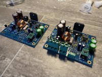
That seems like a great question to ask Audiophonics. They should support their own products. The website for one of them says that the current is limited by the 15 W resistor and in the picture there's a 15 W, 7 Ω resistor. That will limit the current to 230/7 = 32.9 A. That's not an unreasonable value for an inrush current limiter.How does one know what the inrush current is limited to?
Note that 230 V across 7 Ω will result in an instantaneous power of 7.6 kW – or about 500x the rating of the resistor. The power resistors I've come across that have had a peak power rating have allowed for up to 5x overload. So assuming that the Chinese manufacturer used a quality resistor (OK, you can stop laughing now) you're still overloading the resistor by 100x its spec.
Now, the exact power dissipated in the resistor does depend on when in the mains cycle you flip the power switch, so you could get lucky. But I doubt that circuit will last more than a year, assuming you turn the amp off when it's not in use.
I've written quite a bit on soft start designs. You can find it here: https://neurochrome.com/pages/the-ultimate-guide-to-soft-start-design
I had to study the LOP-300 data sheet and installation guide to figure out the rest of your questions. I've included some screen shots so others can see what you're referring to.
A curious thing that I see in the LOP-300 data sheet is that it says "3 max" at the left bottom corner (see page 5). But "3 max" of what?
That means any component pin that protrudes through the circuit board extend past the bottom of the board by a maximum of 3 mm.
I interpret that as: If you want to keep electrical safety Class II you need to provide at least 5 mm of space from the bottom of the board to the chassis panel that you're mounting the supply to. The mylar film is then needed to maintain Class II.
I think you can maintain Class II if you provide enough clearance from the tips of the longest protruding pins to the chassis. You need to provide a minimum of 6.4 mm there, so you should be good if you mount the board on 10 mm long standoffs. In that case you can forego the mylar film.
Also see this note in the data sheet:
You mean this?And what is that plastic screw terminal in the right corner of the schematic below 2 caps for?
That's a trimpot for setting the output voltage.
... and as others have said already, each LOP-300 produces a single voltage so you need two in series to form a bipolar supply.
Tom
Happy 10th anniversary Modulus-86! ... and lovers of the OPA627 rejoice!
The Modulus-86 turns 10 this month and I turn 50. I think that calls for a celebration and I decided the best way to celebrate was to design a special edition of the Modulus-86. When a friend came up with a good handful of OPA627BM in the TO-99 (metal can) and a slightly larger handful of the IC in 8-pin DIP, I knew I had to jump at the opportunity to wring the last bit of performance out of the Modulus-86 topology. These devices are out of production in those DIY-friendly package options, so I'm straying from my usual modus operandi of using only parts that are commonly available off the shelf. But ya know... Sometimes you gotta have a little fun.
These look fun:

These parts came from either a space qualifying lot or from a correlation lot of sorts. That's why some of them have faint markings on them. You can occasionally find the TO-99 version at various distributors. Prices start at $70/each ... if you can find it. As mentioned I also have the DIP version. That one is slightly less expensive at about $50/each. So they're basically carved from solid unobtanium. Also note that they're the 'BM' version, so the high grade ones!
The 10th Anniversary Edition will only be sold as kits. I will have 25 kits available with the OPA627BM in the TO-99 metal can option and 65 kits available with the OPA627BM in DIP-8. Note that the metal can version will need to be soldered into the board whereas the DIP-8 is socketed. If soldering to a $70 IC freaks you out, you should consider the DIP-8 instead. I expect the pricing to land around $340ish for the DIP-8 version and $390ish for the TO-99 version. That's subject to change, of course.
The same friend also gave me a copy of Henry Ott's Electromagnetic Compatibility Engineering. I found Chapter 16 on mixed signal PCB layout especially inspiring and also found inspiration in Bruce Hofer's AES presentations.

As result, the 10th Anniversary Edition of the Modulus-86 features a redesigned PCB with several features included to minimize parasitic coupling for even higher performance. I also employed several of the lessons learned from my recent resistor experiments in this new design.
The prototype performs very, very well. It could be one of the best power amps I've designed to date, but I'll wait to judge until I've had a chance to evaluate the final PCB layout. As always, I'll follow up with a suite of measurements once I'm ready for launch. I expect launch to happen towards the end of this month. I'll announce the launch here and also in my newsletter (subscribe here: https://neurochrome.com/newsletter), and on the Neurochrome Forum.
Tom
The Modulus-86 turns 10 this month and I turn 50. I think that calls for a celebration and I decided the best way to celebrate was to design a special edition of the Modulus-86. When a friend came up with a good handful of OPA627BM in the TO-99 (metal can) and a slightly larger handful of the IC in 8-pin DIP, I knew I had to jump at the opportunity to wring the last bit of performance out of the Modulus-86 topology. These devices are out of production in those DIY-friendly package options, so I'm straying from my usual modus operandi of using only parts that are commonly available off the shelf. But ya know... Sometimes you gotta have a little fun.
These look fun:
These parts came from either a space qualifying lot or from a correlation lot of sorts. That's why some of them have faint markings on them. You can occasionally find the TO-99 version at various distributors. Prices start at $70/each ... if you can find it. As mentioned I also have the DIP version. That one is slightly less expensive at about $50/each. So they're basically carved from solid unobtanium. Also note that they're the 'BM' version, so the high grade ones!
The 10th Anniversary Edition will only be sold as kits. I will have 25 kits available with the OPA627BM in the TO-99 metal can option and 65 kits available with the OPA627BM in DIP-8. Note that the metal can version will need to be soldered into the board whereas the DIP-8 is socketed. If soldering to a $70 IC freaks you out, you should consider the DIP-8 instead. I expect the pricing to land around $340ish for the DIP-8 version and $390ish for the TO-99 version. That's subject to change, of course.
The same friend also gave me a copy of Henry Ott's Electromagnetic Compatibility Engineering. I found Chapter 16 on mixed signal PCB layout especially inspiring and also found inspiration in Bruce Hofer's AES presentations.
As result, the 10th Anniversary Edition of the Modulus-86 features a redesigned PCB with several features included to minimize parasitic coupling for even higher performance. I also employed several of the lessons learned from my recent resistor experiments in this new design.
The prototype performs very, very well. It could be one of the best power amps I've designed to date, but I'll wait to judge until I've had a chance to evaluate the final PCB layout. As always, I'll follow up with a suite of measurements once I'm ready for launch. I expect launch to happen towards the end of this month. I'll announce the launch here and also in my newsletter (subscribe here: https://neurochrome.com/newsletter), and on the Neurochrome Forum.
Tom
Probably as good time as any to say thank you again for your work on the original Modulus-86. It remains the reference amp, I still experiment with various vacuum tube ideas - class A2 is a thing if one can entertain some MOSFET followers, however the Modulus-86 V2.1 with the -HA TO-99 LME49710 is the go-to for a reality check, on Klipsch Heresy Mk1s no less. We play on.
Ah, yes. I remember that whole Rev. 2.0-2.1-2.2-2.3 yoyo going from DIP-8 to TO-99 and back again as TI vacillated on whether to keep the LME49710 around. Then finally settle on just using half of an LME49270/LM4562 in the end. Good times... 🙂
I forgot to mention that the 10th Anniversary Edition will be a drop-in replacement for Rev. 3.0 for those looking to upgrade. That also means it'll drop right into the Modulus Chassis.
Tom
I forgot to mention that the 10th Anniversary Edition will be a drop-in replacement for Rev. 3.0 for those looking to upgrade. That also means it'll drop right into the Modulus Chassis.
Tom
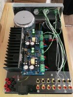
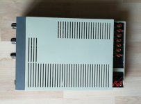
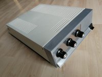
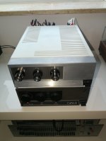
Modulus 86 stereo amp with passive preamp in Mission Cyrus enclosure finally done! Covid, health issues and personal matters made this project way longer than expected, though I knew I'd pull through. It was... an experience and lots and lots of work, many unexpected issues that needed to be found a creative solution for.
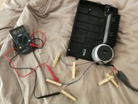
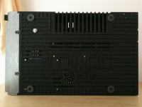
The case was broken, needed to be glued. The heat sink wasn't smooth and level but rough and slightly skewed, needed filing, sanding and polishing. Old heat sink holes needed to be filled with aluminum, new holes drilled and threads cut for mounting the LM3886 and the pcbs.
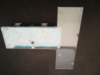
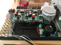
The amp pcbs would't fit between the transformer and backside of the enclosure lid, so I had to creatively sandwich both pcbs. Tom's idea was to mount one pcb upside-down - which would've worked, but when tinkering around in the end I found the sandwich solution which looked even more interesting to me. Also I liked the idea of having one big amp board with all terminals in one row.
To achieve this, some components needed to be soldered to the underside of the pcb. Both pcbs were then connected by their mounting holes, isolated by three thin sheets of acrylic. To get the boards as tight together as possible the solder side was filed down to surface level. To mount the sandwich board to the angled Cyrus heat sink, it was necessary to build a 2nd level mounting board, made of 3mm acrylic, which exactly fits the original Cyrus amp pcb mounting holes.
Additionally, to get enough strength to support the new sandwich board, the 2nd level was mounted on newly fit and cut to the mm stand-offs. Finding the exact correct spots on the black zinc-aluminum bottom plate to drill the new holes/cut new threads wasn't easy at all and ofc I made a few mistakes as the holes needed to be absolutely perfect - otherwise the board would sit angled or under stress. The stand-offs for the psu board were easy to fit though.
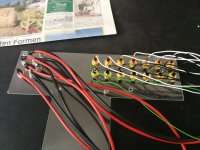
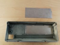
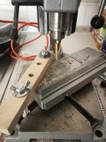
Next was the Cyrus enclosure front which needed an outer and inner metal shielding to allow proper mounting of the stepped volume attenuator, input and output source rotary switches. I just used 0.6 mm steel from the local "Bauhaus" hardware store. I hate metal work, so I was really relieved when the parts were sawed out and filed to fit front and back. Punch-marking and drilling the holes for the switches was a nightmare too ;-) as the front outer and inner metal shielding somehow needed to be held in place to do so. Did I say I hate metal work? Yes, I do, OMG!!!
In the end it was a really satisfying process seeing the build grow and grow and finally being able to put all the handmade parts together. Everything one does with one's hands it's somehow so fulfilling and rewarding.
Designing the passive preamp took a few days as there's also a lot than can go wrong or cause problems, especially with a more advanced signal flow and a tape loop, concerning ground signal flow, ground loops, crosstalk and whatnot... So, soldering the "preamp" was something I managed to procratinate for some weeks before actually doing it, idiotic I know! In the end it just developed nicely and worked right away without any flaw. I used unshielded solid-core copper wire for all internal audio connections. Signal ground was divided as one left and one right summed ground signal for all channels going to the attenuator. All audio connections were soldered with silver solder.
Astoundingly, as space was very constricted inside the Cyrus enclosure to fit the psu board, it'd only fit at the front edge of the sandwich amp board, the space between rectifier and audio signal cabling, about 3-4 cm, seems to be enough to NOT cause any audible problems - my speakers are dead silent on full amp gain, no mains hum at all.
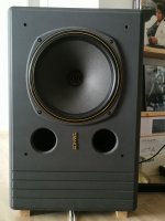
PSU board spits out +/- 34.5 v with this transformer, which is at the upper end but works fine for my 6 to 8 Ohm Tannoys. I'm measuring -0.5 and -0.8 v dc offset, which is nice enough I think. Of course I could still wash the boards with a special cleaner, but does it really matter?!? The amp worked right away, so no errors done, phew...!
Attached a few photos of the build process, description of sound in another post, one word upfront though: exceptional!
Attachments
-
 1-small.jpg335.4 KB · Views: 283
 -
 2-small.jpg805.7 KB · Views: 269
 -
 3-small.jpg219.9 KB · Views: 278
 -
 4-small.jpg482.9 KB · Views: 246
 -
 5-1-small.jpg366.9 KB · Views: 237
 -
 5-2-small.jpg516.6 KB · Views: 269
 -
 6-small.jpg438.4 KB · Views: 289
 -
 7-small.jpg587.1 KB · Views: 282
 -
 8-small.jpg301.8 KB · Views: 271
 -
 9-small.jpg134.5 KB · Views: 254
 -
 10-small.jpg398.3 KB · Views: 252
 -
 11-small.jpg394.8 KB · Views: 251
 -
 12-small.jpg381.5 KB · Views: 261
Last edited:
The outer appearance is not finshed yet, thinking about Nextel grey, black or the classic old QUAD design in grey and orange. But it can wait for now...
Now the most important thing - how does it sound? After having worked in studios as an audio engineer, listening to different passive/active monitoring I didn´t think anything could really suprise my anymore, but Tom's amp does!
The most apparent things to my ears are micro-dynamics and micro-detailing, as in I can now hear the most little volume fluctuation in a modulating voice, micro details of sound that I never heard before. Also a stunning signal separation that actually lets me clearly hear what is what and where. Stereo image is amazing, stereo center is spot-on dead in center, absolutely stable. it´s a joy to listen to that alone.
As many have noted before, at first listening the bass seemed to be slightly polite and held back - but - after one hour of listening more closely yesterday I'd say it's just bloody precise, fast and ultra tight. So, to me, more correct. If I need/want more bass I can use an EQ, but generally I only want to hear what's on a recording or not. So, if bass is too lean than it´s too lean and I want to hear it to correct it, and that the Mod-86 delivers.
All in all I'd say Tom's amp does one thing to 100 %: absolutely nothing! It just amplifies what's there without adding or subtracting anything. That's an absolutely unbelievable achievement if you ask me. But then again I never heard other high-end gear like 50k Accuphase or comparable gear, so maybe that's why I'm so suprised by this little amp.
Anyhow, a friend has class A and IcePower amps and we're going to compare different amps in a few weeks. I'm totally curious about how he'll react to Tom's design. As he has the same Tannoy monitors it'll be a good setup for comparison.
Tom - if you read this - outstanding work! I've never heard a better amp than yours 🙂
One little request, if you'd ever like to design a little phono stage preamp pcb, that could be powered by the power-86 psu board, it'd be the icing on the cake... ;-)
Last edited:
Ah, yes. I remember that whole Rev. 2.0-2.1-2.2-2.3 yoyo going from DIP-8 to TO-99 and back again as TI vacillated on whether to keep the LME49710 around. Then finally settle on just using half of an LME49270/LM4562 in the end. Good times... 🙂
I forgot to mention that the 10th Anniversary Edition will be a drop-in replacement for Rev. 3.0 for those looking to upgrade. That also means it'll drop right into the Modulus Chassis.
Tom
One question: will there be different pcb boards for the DIP-8 and TO-99 versions of the 10th Anniversary, or will there be just one board with spaces for both and the unused space left unpopulated?
Thank you for your writeup, build pictures, and review. I appreciate it. Interesting idea with the overlap between the boards. I keep the parts away from the board edge for manufacturability reasons, so it probably wasn't much that you needed to file off to allow for the overlap.All in all I'd say Tom's amp does one thing to 100 %: absolutely nothing! It just amplifies what's there without adding or subtracting anything. That's an absolutely unbelievable achievement if you ask me. But then again I never heard other high-end gear like 50k Accuphase or comparable gear, so maybe that's why I'm so suprised by this little amp.
I'm a bit surprised by the acrylic piece. Did you need acrylic to prevent an electrical connection? I'd probably made it out of aluminum, but then again, that's what I'm comfortable working with so that drives my choices at times.
Either way, I'm happy your build came together nicely for you.
Oh, I always read this thread even if I don't get a chance to respond immediately. I really appreciate that you took the time to share your experience. Thanks!Tom - if you read this - outstanding work! I've never heard a better amp than yours
I'll see what I can do. 🙂One little request, if you'd ever like to design a little phono stage preamp pcb, that could be powered by the power-86 psu board, it'd be the icing on the cake... ;-)
Tom
There'll be two boards. One for the TO-99 and another for the DIP-8. I thought of doing a combo footprint, but figured it would cause too much confusion. I also thought it would look a bit cheap, and I don't want cheap.One question: will there be different pcb boards for the DIP-8 and TO-99 versions of the 10th Anniversary, or will there be just one board with spaces for both and the unused space left unpopulated?
The boards are making progress on their trek across Canada. They're made in the outskirts of Toronto. So I still expect to be able to launch by the end of the month.
Tom
You're welcome 🙂 When we had the short email exchange last year about the Cyrus enclosure I promised to contribute to this thread when all is done, so I'm happy to finally being able to do so. I just didn't think it would take me so long... But life always seems to find a way.Thank you for your writeup, build pictures, and review. I appreciate it. Interesting idea with the overlap between the boards. I keep the parts away from the board edge for manufacturability reasons, so it probably wasn't much that you needed to file off to allow for the overlap.
I only filed down the solder "blobs" to the surface level of the pcb, so no harm done to the boards at all, they are still original size. It was just done so that the boards wouldn't bend at the solder points when screwed together as a flat sandwich.
I'm a bit surprised by the acrylic piece. Did you need acrylic to prevent an electrical connection? I'd probably made it out of aluminum, but then again, that's what I'm comfortable working with so that drives my choices at times.
Yes, exactly, acrylic just for isolation, also because I already had all the non-isolated banana and RCA sockets. If I'd do it again I'd probably use something else though as acrylic isn't really that stiff, that's why I added/glued small acrylic pieces to the left and right of the RCA socket area as a support. But really, if I'd build an amp again I'd surely use a dedicated new enclosure, adapting to the little Cyrus space and angled heat sink was no joy, but I'm happy it worked out fine of course.
Either way, I'm happy your build came together nicely for you.
Thank you 🙂
Oh, I always read this thread even if I don't get a chance to respond immediately. I really appreciate that you took the time to share your experience. Thanks!
I'll see what I can do. 🙂
Tom
I'll keep an eye on new developments for sure. An MC/MM board by neurochrome would be ace!
Thank you 🙂
Ken
In case some people are looking for reasonably-priced but excellent sounding preamp option for Modulus 86, I can report with happiness that both stock PassDiy Korg B1 and upgraded Korg B1 work and sound fabulous with Modulus 86 (in Quad case)!
 0816241527_HDR by drjlo2, on Flickr
 0816241527_HDR by drjlo2, on Flickr
On my website: www.neurochrome.com
The official launch will be towards the end of the month and I'll post a direct link here (and in my newsletter) once it happens.
Tom
The official launch will be towards the end of the month and I'll post a direct link here (and in my newsletter) once it happens.
Tom
Sitting here listening and enjoying the silky smooth mids with this amp!
I have adapted my favorite OPA1656 as input buffer. Other than that no changes.
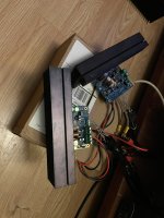
Thinking about using AN-1220 transformer to fit it all into a small case… Right now amp is in prototype mode assembled in a cartoon box.
I have adapted my favorite OPA1656 as input buffer. Other than that no changes.
Thinking about using AN-1220 transformer to fit it all into a small case… Right now amp is in prototype mode assembled in a cartoon box.
Attachments
- Home
- Amplifiers
- Chip Amps
- Modulus-86 build thread
