Mine are two-fluted as well. Plain ol' jobber drills. I find that a 2 mm drill bit will catch in the punch mark so it centres where I want it. But I also hand-hold the workpiece (yeah, yeah. Safety-smafety! 🙂).Perhaps it is the nature of the bit I am using, which has two cutting furrows.
I used to do a lot more chassis customizations by hand than I do now. These days I just order a couple from ModuShop or Takachi and sell what I don't use. It sure is nice to unpack a box of chassis and have a finished amp a few hours later.
Also, at the current outdoor temperatures working in the garage is a non-starter. It was -36 ºC at 9AM this morning. Tomorrow should be a balmy -12C. 🙂
Tom
Having grown up in Hawaii, I can’t imagine such temps. Even living in Washington DC area, coldest we’ve ever experienced is 0 degrees F.
And yes, way better to just begin using an already punched box.
And yes, way better to just begin using an already punched box.
I grew up in a costal climate. The lowest temperature I experienced until I moved inland was -17C one morning in 1987. I observed at the time that people dressed like bank robbers. 🙂
I do remember the first time I saw below -30C on the thermometer. My reaction was, "wow! Last I saw temperatures like that was on the display of a CO2-chilled climate chamber at TI" 🙂 #inlandLiving
Tom
I do remember the first time I saw below -30C on the thermometer. My reaction was, "wow! Last I saw temperatures like that was on the display of a CO2-chilled climate chamber at TI" 🙂 #inlandLiving
Tom
Never heard about a drill stand. Definitely getting one of those. Like you said, amp cases are not the only things being drilled (please don't read this out of context).I drilled many chassis with the drill stand my dad had. They came together nicely.
How do you operate the drill stand? It has a handle like you're supposed to grip it there, but you also need a hand to control the rotation speed.
I wouldn't mind investing in a drill press, but you can't deflate them and I don't have good space.
About the DIY machining precision, I've found it hard to get accurate results too. I use a center punch and 3mm pilot holes. Smaller drills are broken by me too often but I tend to tense my muscles too much for this type of job. My motor cycle instructor got frustrated with me trying to crush the handles too. Maybe a drill press would help.
If I have to increase the size of the pilot holes to 6mm or 8mm for example, I lose a lot of accuracy in that, sometimes a few mm if I'm unlucky. I bet it's the same as Halauhula mentioned, same type of drills too.
All this also comes with the time required, that's really prohibitive for me. OK, maybe 42 ventilation holes in 3mm steel for my LM3886DR wasn't the brightest idea either. The drilling of that one was a full weekend.
If I'm drilling a panel, I like to put a piece of wood under it, then clamp the wood and the panel to the edge of a table with a glue clamp. There are affordable ones with quick operation nowadays.
Do you folks apply any oil for drilling or tapping?
The bank robbers gave me a laugh. During a COVID peak, a police car passed me by when I was dressed as a bank robber, or rather a highwayman.
Make sure your power drill has the needed accessory collar. Example:Never heard about a drill stand. Definitely getting one of those.
Oh, boy. I could take my answer in quite a few direction with a question like that. 🙂Do you folks apply any oil for drilling or tapping?
OK, so... With aluminum I use A-9 Aluminum Cutting Fluid. In the past I've used denatured alcohol. It works well as a cutting fluid, but I'm not a fan of the flammable fumes and such. I hear kerosene works as well. Of course that's flammable too, but at least it isn't quite as volatile as alcohol.
Personally I'd approach an industrial supply place and see what they have. I bought my can of A-9 at Tacoma Screw back when I lived in the Seattle area. That li'l can has lasted at least 15 years now.
For drilling steel I use regular sewing machine oil.
Large holes (Neutrik D-shell for example) are easily drilled with a hole saw. I bought a carbide-tipped one at Bezos Bookstore for not much money. I've drilled both 1 mm steel and 1-3 mm aluminum panels with that saw and it's still sharp. Just go slow, use plenty of cutting fluid, and clamp the workpiece.
Tom
Tom

Is there a post detailling the changes in v3 or a comparison of performance to older versions? ThanksThere are plenty of completed Modulus-86 in this thread. I thought yours was the first Rev. 3.0, but it turns out mkrawcz beat you to it: Post #5691.
Oh, probably...
Modulus-86 Rev. 3.0 features a complete redesign of the front-end of the amp. I eliminated the THAT1200 as that limited the noise performance of the circuit. I also took out the DC servo as I was able to get stellar DC specs by other means. That lowered the build cost.
I also changed the power stage to be a differential amp (balanced in, single-ended out).
The end result is an amp with even better THD+N (due to the reduction in +N) and lower build cost. That's Rev. 3.
Tom
Here's the full revision history. This is from the Modulus-86 Rev. 3.0 design documentation:

Tom
Tom
I was reading about the XLR pin 1 problem and read that pin 1 should be connected to the chasis only. I remember building my mod86 and soldering the XLR tab to pin 1 but also running the cable to the mod86 ground. Is there something fancy in the design or have I mis wired something (seems to work ok) 🙂
(Also not clear to me as surely the chasis is all connected so its the same ground? )
(Also not clear to me as surely the chasis is all connected so its the same ground? )
The best source for information about the "pin 1 problem" (which isn't really a problem IMO) is AES48-2019. It's pretty clear from the figures in the standard that Pin 1 should connect to the chassis and that the EMI filter should connect to Pin 1. That's exactly what I recommend for the Modulus-86.
Tom
Tom
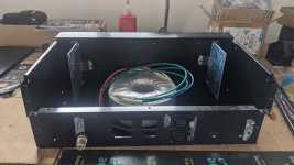
i made some progress, thank you @tomchr and @asuslover for your advice. i had to get some neopreme washers for the audio jacks to fit, a drill/tap set, cutting oil, a file, and my uncle had a drill press i was able to borrow. i think i do the rest with hand tools now.
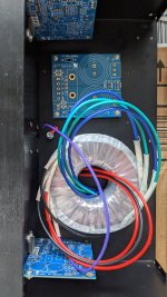
i was gettng frustred workign with hand tools and their speed, so i just went the shortest route. since transformer is in the center, the input is right next to it. i dont want to be making those holes again(too late now... lol) so hoping for the best.
thinking about relocating the power86 to the left so the LED power light has a shorter run, theres a place to run a LED to the front of the chasis on the left side. i need to check for clearance between the mod86 and the power 86 now.
Attachments
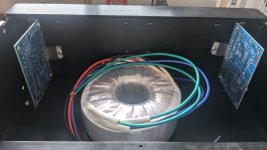
I don't have a great sense of depth in the pictures, but it looks like the components on the Power-86 will interfere with the Modulus-86 board. I would scoot it as close to the rear panel as possible and possibly rotate it 90º. Keep the rectifier away from the inputs to the amp.
You could also possibly scoot the transformer further to the right and fit the Power-86 in next to it.
The connections to the power LED would be at the absolute bottom of my list of things to worry about.
Tom
You could also possibly scoot the transformer further to the right and fit the Power-86 in next to it.
The connections to the power LED would be at the absolute bottom of my list of things to worry about.
Tom
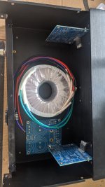
thanks for the advice tom. i remember you mentioned you want to keep the amplifier parts away from the inputs. so the rectifier is where we can maximize that layout i moved things around to do this. about 7 more holes to drill and i can start mounting everything!


Actually, it's the rectifier that you want away from the inputs. The transformer wiring should be away from the inputs as well.i remember you mentioned you want to keep the amplifier parts away from the inputs.
The issue there is that the transformer wiring and rectifier carry some pretty spiky currents, especially when the amp is idle or providing low output power. That's because the reservoir capacitors don't discharge much so the conduction angle (i.e., the proportion of the sine wave cycle where the diodes conduct) becomes tiny and, thus, the charging current very high. That current can couple inductive into stuff.
Inductive coupling is proportional to the loop area, so keep that small. That's why I recommend that you bundle the transformer wires.
It looks like you've found a good compromise. I'd go with that.
Tom
i am going through the content for grounding, is there a difference using a mounting hole on the power 86 for ground vs a dedicated bolt/nut on the chassis?

can i use a corner of the power 86 mounting to do the same as the ISS above? or better yet, is there a best practice?
ahh i see this from the quad build:

can i use a corner of the power 86 mounting to do the same as the ISS above? or better yet, is there a best practice?
ahh i see this from the quad build:
@peterinhawaii
Read part 7 of ESP’s doc on grounding. The whole article is excellent, but part 7 gives you the details you need. I quote:
Of course this is DIY and you are free to do what you want. But I always think about safety issues particularly if I sell the amplifier or if something gets dislodged during shipping. I strongly recommend using a locknut to fastidiously adhere the chassis ground lug to the chassis.
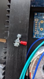
Here is an example from one of my previous builds:

Best,
Anand.
Read part 7 of ESP’s doc on grounding. The whole article is excellent, but part 7 gives you the details you need. I quote:
Do not use the earth connection as mounting for any other panel or component - it must be dedicated to the task of providing a safety earth point. If a component mounting bolt is used, at some stage it may be disconnected by a service (or other) person, which means that the apparatus is unsafe until everything is (hopefully) put back where it belongs - this does not always happen.
Of course this is DIY and you are free to do what you want. But I always think about safety issues particularly if I sell the amplifier or if something gets dislodged during shipping. I strongly recommend using a locknut to fastidiously adhere the chassis ground lug to the chassis.
Here is an example from one of my previous builds:
Best,
Anand.
The mains protective earth terminal should go directly to a solder lug mounted directly on the chassis, secured with a machine screw and lock nut. The point of this is to ensure that if a mains live connection ever comes into contact with the chassis, the fuse will blow before the user is electrocuted.
EMI ground returns, input ground references, etc. can be connected however you'd like. In some of my builds I use a solder lug mounted at the ISS as the ground return for the electrostatic shield in the power transformer. The purpose of the electrostatic shield is to capacitively couple any RF energy from the mains to ground. It is not a safety thing. The important piece there is that the connecting wire is as short as practical. In my case that meant using the mounting screw for the ISS.
Tom
thank you @tomchr and @poseidonsvoice
will use your guidance
i also found this thread
https://www.diyaudio.com/community/...ay-to-ground-the-modulus-86-amplifier.392555/
will use your guidance
i also found this thread
https://www.diyaudio.com/community/...ay-to-ground-the-modulus-86-amplifier.392555/
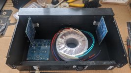
i went to the hardware store i got a bolt with some locking hardware. im not sure where is a good place to put the ground yet. im leaning towards the IEC plug so its closer to the mains, rotate the transformer so the shielding wire is closer as well
Attachments
- Home
- Amplifiers
- Chip Amps
- Modulus-86 build thread