There's a thread where folks share CAD drawings for Modushop, to create a library. Great idea!
I received a PM asking me to share the drawings for the build I posted. You can view my drawings, and some additional pointers on my CAD experience, in this post:
https://www.diyaudio.com/community/...nch-design-library.406885/page-2#post-7555610
I received a PM asking me to share the drawings for the build I posted. You can view my drawings, and some additional pointers on my CAD experience, in this post:
https://www.diyaudio.com/community/...nch-design-library.406885/page-2#post-7555610
Last edited:
The Modulus-86 build is gorgeous. I like how the hidden wiring makes for a nice and clean look. I may also copy your idea with the bottom-mounted power switch.Finished Mod-86 amp, looks great, sounds great, great experience with Neurochrome support and with building using Neurochrome products. Highly recommended! Pictures at the end.
One note, though: I'm not a super fan of running the wires through the metal plate without a grommet. Vibration will cause the wires to fray over time. It's only the low-voltage wiring, so it's not a safety issue. It's just one of those things that'll make a difference between this amp lasting 10 years and 50 years. 🙂
Thanks for sharing your pictures and experience. I appreciate it.
Tom

Thanks Tom! Grommets..

Must be my lack of tube experience. I used to see grommets all over the place in DIY tube designs. Had I thought of it, I would have used them. Some wires received some chafing as punishment for their resistance. The isolation is quite thick on these though, and I don't have a big vibrating transformer, so I'm not too worried for now. Still a good thing to improve on and learn from.
The verdict is still out on the inner plate. Clean wiring is awesome. Having to drill the plate (Modushop can't machine it for you) if the holes for your specific parts aren't aligned is a lot of extra work, especially if you don't have a column drill (I don't). The plate is steel I think, definitely not aluminum. It also eats some of your available space. The regular Dissipante I used isn't the smallest chassis but there are still constraints.
Another detail I forgot to mention: I sanded literally all the contact surface between anodized parts and the blank bracket, using a precision drill/grinder. I wasn't getting good conductivity with the black chassis otherwise, as has been my experience with another type of Modushop chassis too. That's cool about the bracket, you can hardly tell I did this from the photos, the bracket hides most of the sanded surface. I tried sanding small parts but that wasn't enough, in my experience this was the only way to make sure. You could also have the anodization removed by Modushop I guess, but then I would have to customize almost every chassis part, a costly exercise.
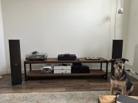
In the attachment is a photo of the amp in the complete system. Currently just the streamer, amp and speakers are connected.
Must be my lack of tube experience. I used to see grommets all over the place in DIY tube designs. Had I thought of it, I would have used them. Some wires received some chafing as punishment for their resistance. The isolation is quite thick on these though, and I don't have a big vibrating transformer, so I'm not too worried for now. Still a good thing to improve on and learn from.
The verdict is still out on the inner plate. Clean wiring is awesome. Having to drill the plate (Modushop can't machine it for you) if the holes for your specific parts aren't aligned is a lot of extra work, especially if you don't have a column drill (I don't). The plate is steel I think, definitely not aluminum. It also eats some of your available space. The regular Dissipante I used isn't the smallest chassis but there are still constraints.
Another detail I forgot to mention: I sanded literally all the contact surface between anodized parts and the blank bracket, using a precision drill/grinder. I wasn't getting good conductivity with the black chassis otherwise, as has been my experience with another type of Modushop chassis too. That's cool about the bracket, you can hardly tell I did this from the photos, the bracket hides most of the sanded surface. I tried sanding small parts but that wasn't enough, in my experience this was the only way to make sure. You could also have the anodization removed by Modushop I guess, but then I would have to customize almost every chassis part, a costly exercise.
In the attachment is a photo of the amp in the complete system. Currently just the streamer, amp and speakers are connected.
Attachments
Yeah. I'm not sold on the 'holey' plate either. It's kinda nice not to have a bunch of screw heads on the bottom panel, but I don't look at that very often. The biggest value-add for me is probably that the mounting bolt for a toroidal power transformer can be hidden from view, but that's not an issue when you use an SMPS.
I don't like imposing arbitrary restrictions on my PCB layouts so I decided from the start that I wasn't going to follow ModuShop's pattern. Also, the chassis aren't super precise anyway, so I'd be worried about ending up with boards that almost fit.
Tom
I don't like imposing arbitrary restrictions on my PCB layouts so I decided from the start that I wasn't going to follow ModuShop's pattern. Also, the chassis aren't super precise anyway, so I'd be worried about ending up with boards that almost fit.
I like your audiophile pooch.In the attachment is a photo of the amp in the complete system. Currently just the streamer, amp and speakers are connected.
Tom
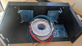
wow i had no idea i would be stuck in limbo when it came to working on this build. i have a number of to-dos still.
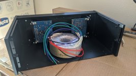
had to wait 45 days before the mounting brackets came to even start mounting the boards.
the toroidal transformer is way bigger than expected, but i think i got space. I want to center it to keep the weight centered lol
now i understand why some builds takes months or years for some to finish!
happy new year everyone
Attachments
Did you consider any sort of preamp/volume control between the Wiim and the amp?Thanks Tom! Grommets..
View attachment 1255529
Must be my lack of tube experience. I used to see grommets all over the place in DIY tube designs. Had I thought of it, I would have used them. Some wires received some chafing as punishment for their resistance. The isolation is quite thick on these though, and I don't have a big vibrating transformer, so I'm not too worried for now. Still a good thing to improve on and learn from.
The verdict is still out on the inner plate. Clean wiring is awesome. Having to drill the plate (Modushop can't machine it for you) if the holes for your specific parts aren't aligned is a lot of extra work, especially if you don't have a column drill (I don't). The plate is steel I think, definitely not aluminum. It also eats some of your available space. The regular Dissipante I used isn't the smallest chassis but there are still constraints.
Another detail I forgot to mention: I sanded literally all the contact surface between anodized parts and the blank bracket, using a precision drill/grinder. I wasn't getting good conductivity with the black chassis otherwise, as has been my experience with another type of Modushop chassis too. That's cool about the bracket, you can hardly tell I did this from the photos, the bracket hides most of the sanded surface. I tried sanding small parts but that wasn't enough, in my experience this was the only way to make sure. You could also have the anodization removed by Modushop I guess, but then I would have to customize almost every chassis part, a costly exercise.
In the attachment is a photo of the amp in the complete system. Currently just the streamer, amp and speakers are connected.
I have read some posts that the volume on some DACs didn't stay fixed and put out max volume.
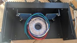
Dang! Is that a 500 VA type?the toroidal transformer is way bigger than expected, but i think i got space. I want to center it to keep the weight centered lol
Tom
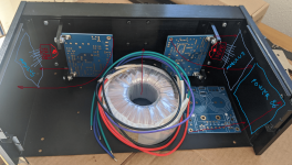
i bought the AS-2222 - 200VA 22V Transformer. i went over to check the label on the transformer to double check too lolDang! Is that a 500 VA type?
Tom
@asuslover
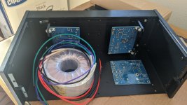
Thanks for the suggestion! i was thinking about mounting the power 86 on the side, but didnt consider the modulus boards there too. ill give it a look to see if i can.I would not use those T shape bars.
i am prepared to drill into the chassis, but not into the heatsink, so i am not sure how to mount the lm3886s on it
i was looking at how the chassis was designed for the heatsink. Its a heatsink then a back plate. I am going to take off the back plate, curious to see if the whole backplate needs some TIM too. the backplate provides mounting holes for the rest of the chassis to come together. they are not directly mounted to the heatsink if i am right.
Last edited:
Wow. That transformer certainly looks towering in the picture. Oh, well. It's a good transformer.
Tom
Tom
i can flip the T bar around and mount the boards to the other side to give the center area more room. i only oriented the brackets in that direction as theres more material to where the LM3886 mounts to. if you flip it around, the are more holes and less bracket material to touch the lm3886.I would not use those T shape bars.
it would give clearance like this user did : https://www.diyaudio.com/community/threads/modulus-86-build-thread.267802/page-293#post-7059344
i tried to do a mock up to mount the modulus boards on the side, it would require quite a bit of modification to the chassis and drilling into the heatsink and the outer blocks.
is there a signal based issue or something that impacts performance if i put the transformer that close to the mod86 boards?
@peterinhawaii I like your chassis. You'll finish it somehow. I'm no hero doing drilling by hand so I avoided heat sinks and tapping so far. One route I could have gone was investing in a column drill, and learning how to tap and practicing a bit. I decided I enjoy mechanical work less and up front design more. This was part of my motivation to learn QCAD.
For a one-off you could also look for some help, maybe a machine shop in your area? Your build becomes DIMS (Do It Machine Shop) instead of DIY though.
For home-drilling, Neutrik sockets are nice (XLR, RCA, Speakon). You need one big hole and two small holes. The socket is a bit broader than the required holes, so you can hide some inaccuracies or messy drill work.
I don't like trusting software. I used to do a bit of consulting at a company that designs IC's for medical and space purposes. They always complained to me about IT systems not being finished when they're delivered. They're shipped with software with bugs that have to be fixed afterwards, you hope. You can't do that with EE. If you're going into production, you're gonna have a bad time if you made a design error. I guess I'm lucky I'm in IT, so I don't have to deliver finished solutions 🤔
Back to the topic at hand: the Wiim has a handy feature where you set the max volume in the app, as a separate setting. Afterwards, the regular volume control can't exceed that limit. It actually changes the scale of the regular volume control, making it less sensitive over the entire remaining range.
Another simple solution would be to manually power on the amp only after you know the DAC is running with a safe volume setting. Sucks if you like to work with a 12 V trigger though.
Ideally you don't put anything in the signal path you don't need. Preamps can be required for other reasons, but if you only listen to digital and your gear is OK impedance wise I think it's nice to put the DAC straight on the power amp. I wonder if you could implement some protection in a DIY power amp, that doesn't impact sound negatively in any way. Maybe attenuate to a safe level until a manual override is given, or even just delaying power on to a minute or so in a soft start to give you some time to set the DAC volume first. None of this seems ideal either though.
For a one-off you could also look for some help, maybe a machine shop in your area? Your build becomes DIMS (Do It Machine Shop) instead of DIY though.
For home-drilling, Neutrik sockets are nice (XLR, RCA, Speakon). You need one big hole and two small holes. The socket is a bit broader than the required holes, so you can hide some inaccuracies or messy drill work.
This is actually a very interesting question, that I haven't given much thought before. Pretty scary implications too. If you take a "real" preamp with a volume pot out of the picture, this concern can be extended to any digital volume control. Some DAC's explicitly state they memorize the last setting, but that could fail in multiple ways.Did you consider any sort of preamp/volume control between the Wiim and the amp?
I have read some posts that the volume on some DACs didn't stay fixed and put out max volume.
I don't like trusting software. I used to do a bit of consulting at a company that designs IC's for medical and space purposes. They always complained to me about IT systems not being finished when they're delivered. They're shipped with software with bugs that have to be fixed afterwards, you hope. You can't do that with EE. If you're going into production, you're gonna have a bad time if you made a design error. I guess I'm lucky I'm in IT, so I don't have to deliver finished solutions 🤔
Back to the topic at hand: the Wiim has a handy feature where you set the max volume in the app, as a separate setting. Afterwards, the regular volume control can't exceed that limit. It actually changes the scale of the regular volume control, making it less sensitive over the entire remaining range.
Another simple solution would be to manually power on the amp only after you know the DAC is running with a safe volume setting. Sucks if you like to work with a 12 V trigger though.
Ideally you don't put anything in the signal path you don't need. Preamps can be required for other reasons, but if you only listen to digital and your gear is OK impedance wise I think it's nice to put the DAC straight on the power amp. I wonder if you could implement some protection in a DIY power amp, that doesn't impact sound negatively in any way. Maybe attenuate to a safe level until a manual override is given, or even just delaying power on to a minute or so in a soft start to give you some time to set the DAC volume first. None of this seems ideal either though.
There's definitely value in just throwing money at ModuShop and getting a quality chassis in the mail a few days later. Even across The Atlantic it rarely takes more than a week for the machined chassis to arrive.I'm no hero doing drilling by hand so I avoided heat sinks and tapping so far. One route I could have gone was investing in a column drill, and learning how to tap and practicing a bit. I decided I enjoy mechanical work less and up front design more. This was part of my motivation to learn QCAD.
A column/pillar drill (aka drill press) is not that expensive. We had one of those $50 Chinese ones in the back room at TI when I worked there. It was pretty bad, but you could drill holes with it. It's better than no drill press, but if that's your budget and you already have a power drill, you might look into getting a drill stand instead.
I drilled many chassis with the drill stand my dad had. They came together nicely.
I dropped $300 on the JET JDP-12 drill press that I have. It's definitely a budget drill press, so things like the depth stop is a bit awkward to use but it does work. I think that drill press is at least 15 years old now and it still runs smoothly. It is by far the tool I use the most.
Unless you're able to bribe the machine shop with a case of beer or something you'll also find that gets really expensive fast. For my retail brand, Tom Christiansen Audio, I had a local machine shop machine a rectangular opening in two chassis panels and machine a piece of acrylic to fit the hole. They then engraved "SAMPLE NOT FOR RESALE" into the acrylic. This is pretty simple stuff. Things I could do in a few hours if I had a milling machine. I forget the exact amount they charged but it was on the order of $400. They also screwed up so the window doesn't sit flush with the panel and they engraved the wrong text (NOT FOR SALE rather than NOT FOR RESALE). And this is a reputable local shop. I was not impressed and won't go back.For a one-off you could also look for some help, maybe a machine shop in your area? Your build becomes DIMS (Do It Machine Shop) instead of DIY though.
The same shop also botched two panels where all they had to do was to make a rectangular hole a bit larger. Instead of working from the CAD file I provided they printed out a paper copy and the milling machine operator misread the drawing. What a sh*t show.
Stuff like that makes me appreciate companies like ModuShop and Takachi which get the job done right the first time.
But if you find a machine shop that's reasonably competent you can probably get good work done. But you may be better off by becoming a member of a makerspace so you can use their tools.
The Neutrik D shell is actually pretty easy to dril by hand. Measure and make punch marks for the three holes. Then drill two of them to 2.5 mm (for M3x0.5 mm threads) and drill the third to 4-5 mm. Then use a carbide tipped hole saw for the 24 mm hole.For home-drilling, Neutrik sockets are nice (XLR, RCA, Speakon). You need one big hole and two small holes. The socket is a bit broader than the required holes, so you can hide some inaccuracies or messy drill work.
Tom
I have an inexpensive drill press and I am finding that without a drill press vice, or taking time to fabricate a jig to align a chassis panel against, it is very difficult to get accurately drilled holes. When you look at the cost invested for tools and materials, it is difficult to justify the $ spent for the average hobbyist with 1 or 2 chassis to drill. Way better to just get Modu-U-Shop or Par Metal to do the work, as they are experienced in drilling their chassis panels. And, for Mod-U-Shop, offer a lot more services that a local machine shop probably cannot provide.
That is why I’m trying to address what appears to be the one big barrier preventing hobbyists from getting machining done by Mod-U-Shop and Par Metal: the library of templates.
That is why I’m trying to address what appears to be the one big barrier preventing hobbyists from getting machining done by Mod-U-Shop and Par Metal: the library of templates.
Curious: What makes it hard? I'm trying to understand. I'm not here to argue. If I can understand the issue I might be able to better show people how to machine a chassis as that seems to be a major sticking point for many.I have an inexpensive drill press and I am finding that without a drill press vice, or taking time to fabricate a jig to align a chassis panel against, it is very difficult to get accurately drilled holes.
I just make a punch mark with a centre punch, drill a pilot hole with a 2 mm drill bit, and go from there. I hold the workpiece by hand when I drill smaller holes. I have no trouble getting to something like ±0.2 mm precision with that method. I mark the panel with a fine point permanent marker first using a machinist's ruler. I get that it's not the precision you'd get from a machine shop but the end result looks good.
True. Assuming that's all you ever drill. I use my drill press for many projects around the house.When you look at the cost invested for tools and materials, it is difficult to justify the $ spent for the average hobbyist with 1 or 2 chassis to drill.
Tom
I had thought about a Neutrik PowerCon to avoid cutting square holes, its the same round holes as for the XLR etc.

In the end , I decided to try out modushop, as discussed, by the time I purchased a drill mount and mashed/messed up a square hole I might as well have them do it properly.
I note a number of cases have the IEC hole already drilled which makes it easier. Audiophonics have a few cases if you are in Europe.
I love the Neutrik XLR and speakON connectors for that exact reason. Three round holes (one cut with a hole saw). Bam! Done.
Making square holes is not as hard as it might seem, but it's definitely more work than plunging through a panel with a hole saw.
Having the holes machined for the connectors is nice ... if you intend to use the same connectors. I do offer a fully machined chassis for the Modulus-86 and -286: https://neurochrome.com/collections/connectors-parts/products/modulus-chassis
Tom
so if i get a drill bit/tap, i can mount the mod86 boards directly to the heatsink and just drop the brackets. i have an issue finding a cheap metric drill guide vs a drill press. I think i found a M4 one, but didnt find a m3 drill guide yet if i go down this path. I did confirm that the heatsink is 2 peices attached to the plate. so i bet there is thermal conductivity efficiency loss since theres no TIM
i can use an existing m4 hole from the heatsink, drill another M4 into the heatsink, then I need to drill 2 more M3 holes on the side of the case + whatever size the lm3886 hole is
has anyone used these drill/tap in the same bit? i havent seen a video yet if people use these with drills or do everything by hand.
I wouldn't drill and tap with the same bit. Drill bits and taps are pretty affordable, so it shouldn't break the budget to buy a set. You'll need a 2.5 mm drill bit for M3x0.5 and a 3.3 mm bit for M4x0.7.
Tom
Tom
@tom:
Getting the bit accurately centered into the center punch hole, even enlarged with a larger center punch, is an issue. Perhaps it is the nature of the bit I am using, which has two cutting furrows.
Holding the chassis panel to be drilled without a jig or vice, with sufficient strength to prevent the panel from twirling, and turning the handles of the press to lower the bit, often results in slight shifting.
Using a hole saw exacerbates the problem. I am using lubricant: kerosene.
I really need to buy a drill vise and/ or make a jig with bolts and a length of wood, if I am going to continue trying to do chassis, but it just seems easier, to have it done for me. I am learning the Front Panel Express software.....
- Home
- Amplifiers
- Chip Amps
- Modulus-86 build thread