Looks like you are missing gain setting resistors R14 for both channels.Thanks Tom, I also had a RPS-300-27 on hand so swapped that in instead. Amp is up and running. Voltages on both channel look good, DC offset on both look good. However, for some reason the left channel is quieter than the right. Note: using shielded RCAs not XLRs.
Also, missing decoupling cap for LM317/337.
I wonder if it fine to replace LM317 LM337 regulator resistors with 120R and 1.4k?? , still getting 16V with those...
I'm guessing you mean R9 and R15. With the 24 kΩ as specified on the BOM you'll have 48 kΩ input impedance. If you use 47 kΩ you'll have 94 kΩ input impedance.
- input impedance resistors to 47k
Tom

As long as you get ±17 V or below you're good. I normally design for ±16 V to allow for parts tolerances (especially the tolerance of the reference voltage in the LM317/337).I wonder if it fine to replace LM317 LM337 regulator resistors with 120R and 1.4k?? , still getting 16V with those...
Tom
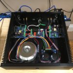
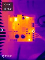
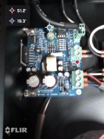
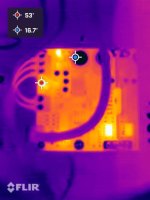
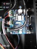
Hi, See attached. I took some photos of the Modulus-86 boards with a FLIR camera. The amp had been running at a "comfortable listening volume" for about 30 minutes. Some components such U2, U3, U4, U5 are warmer than others as expected, but otherwise looks good to me. The heatsinks are keeping the LM3886's as cool as the opposite side of the pillow. 😎
Attachments

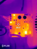
Awesome! Would you happen to have the temperature scale used in those images? Obviously the ICs are warmer, but without the scale it's impossible to tell whether they're 30º or 200º. I suspect they're much, much closer to 30º than to 200.. 🙂I took some photos of the Modulus-86 boards with a FLIR camera.
Tom
Hi Tom, Thanks for your feedback. The FLIR app will display the temperature range and colour gradient on the phone screen, but won't put it into the
photo. Only way I can find to show the temperature range in the photo is to enable the highest and lowest spots. 🤷♂️
photo. Only way I can find to show the temperature range in the photo is to enable the highest and lowest spots. 🤷♂️
Attachments
I'm surprised that the app doesn't have an option to enable the scale.
I still appreciate the IR images though. I use a Fluke IR probe for temperature measurements. It gives me numbers but not the colourful pictures.
Tom
I still appreciate the IR images though. I use a Fluke IR probe for temperature measurements. It gives me numbers but not the colourful pictures.
Tom
So I got tired of the power consuming X-SLAPS, they needed fans and also malfunctioned a lot.
For example blowing the pre-amplifiers op amps. And then I haven't even mentioned the high distortion levels.
So why not look at some of Brian Bell's design form Chipamp.com that I had laying around.
But I was not impressed by their performances.
Then I came across Tom's Modulus-86; the power of a LM3886 with the performance of a LM4562.
So I ordered ten PCB and ordered ten sets of component from Mouser, I already had ten LM3886T from an old unfinished project.
I need ten amplifiers as I have an active four way speaker setup with dual subwoofers. The amplifers are driven directly by an eight channel exaSound e38 DAC, also from Canada. The two sub woofers share one channel a side using an RCA Y cable.
Then the PCBs got stuck in Swedish Customs for a month! The postal services' portal for payment was down.
Long overdue, they finally showed up:

Enough of the pre-story. The build was easy.

I had some PSUs from chipamp, Carlos Felipe's Snubberized desgn, that I harvested form the former chipamp amplifiers.
My first measurements on the lab bench with a 2x24 VAV tranformer resulted in these measurements, distortion at 1 W output power:
 Stepped from level at 1 kHz, 0,2 dB per step from -29 dB (0,25 W output power) to -6,0 dB (the output clips at -6.2 dB and 47,6 W output power) :

I used a EMU0204 as DAC/ADC and had a 7.5 ohms resistor as load. I used the recommended RCA to XLR cable as input.
More to follow shortly.
For example blowing the pre-amplifiers op amps. And then I haven't even mentioned the high distortion levels.
So why not look at some of Brian Bell's design form Chipamp.com that I had laying around.
But I was not impressed by their performances.
Then I came across Tom's Modulus-86; the power of a LM3886 with the performance of a LM4562.
So I ordered ten PCB and ordered ten sets of component from Mouser, I already had ten LM3886T from an old unfinished project.
I need ten amplifiers as I have an active four way speaker setup with dual subwoofers. The amplifers are driven directly by an eight channel exaSound e38 DAC, also from Canada. The two sub woofers share one channel a side using an RCA Y cable.
Then the PCBs got stuck in Swedish Customs for a month! The postal services' portal for payment was down.
Long overdue, they finally showed up:
Enough of the pre-story. The build was easy.
I had some PSUs from chipamp, Carlos Felipe's Snubberized desgn, that I harvested form the former chipamp amplifiers.
My first measurements on the lab bench with a 2x24 VAV tranformer resulted in these measurements, distortion at 1 W output power:
I used a EMU0204 as DAC/ADC and had a 7.5 ohms resistor as load. I used the recommended RCA to XLR cable as input.
More to follow shortly.
The PCB mounting holes didn't match the heatsink's "valleys", so I mounted them on a piece of aluminium:

Cut the parts for the chassis with my plasma cutter:
Welded the parts together and spray painted the finished chassis black.
Mounted the transformer and the PCB:

Back:

Front, the plaque looks a little bit stringy:

Made the connections:

Here's all five chassis up front:

And together with the HTPC and DAC at the top:

Cut the parts for the chassis with my plasma cutter:
Welded the parts together and spray painted the finished chassis black.
Mounted the transformer and the PCB:
Back:
Front, the plaque looks a little bit stringy:
Made the connections:
Here's all five chassis up front:
And together with the HTPC and DAC at the top:
Yes, as it has passive cooling it is dead silent. I opted for the CD drive as I then still ripped CDs. Nowadays it is obsolete as I am using Roon/Qobuz.I like the Streacom HTPC. I have the same one without the CD drive. Looks good.
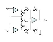
I noticed that it seems like nobody is using the gain resistor R14 for their builds.
Is it on purpose and am I missing something?
I thought the topology is the instrumentation amp, and the gain resistor is used for two unity buffers before the difference amp?
Is it on purpose and am I missing something?
I thought the topology is the instrumentation amp, and the gain resistor is used for two unity buffers before the difference amp?
Attachments
Congratulations on completed project! Looking sleek!😎The PCB mounting holes didn't match the heatsink's "valleys", so I mounted them on a piece of aluminium:
View attachment 1194966
Cut the parts for the chassis with my plasma cutter:
Welded the parts together and spray painted the finished chassis black.
Mounted the transformer and the PCB:
View attachment 1194969
Back:
View attachment 1194970
Front, the plaque looks a little bit stringy:
View attachment 1194971
Made the connections:
View attachment 1194972
Here's all five chassis up front:
View attachment 1194974
And together with the HTPC and DAC at the top:
View attachment 1194975
 too.
too.- Home
- Amplifiers
- Chip Amps
- Modulus-86 build thread