A couple questions, I'm getting around to placing the hopefully last couple orders. First: Which type of tap should I use when tapping the heatsinks? How deep should I drill the hole? I'm using the Dissipante 3u heatsinks, with two holes mounted to the heatsink with brackets, and the LM chip will have a keratherm red backing with an insulating washer and m3 SHCS. Planning on using the same screws throughout.
My other question is whether it matters if my standoffs are aluminum or plastic?
My other question is whether it matters if my standoffs are aluminum or plastic?
Sorry for stating the obvious, but I'm not sure where to start on your question.
The taps should match the screws you plan to use. The drill diameter should match the tap. If you're using metric hardware, I recommend M3x0.5mm. The appropriate drill for that is 2.5 mm. For Murican hardware, #4-40 would be my go-to. #6-32 might work too. You'll have to look up the appropriate drill bit that fits the tap.
I generally set the depth stop on my drill press such that the drill leaves 0.5-1 mm of thickness left in the heat sink. Then I use a bottom tap to get as many threads as I can within the bore. I usually end up with 6-7 mm thread depth. I use spiral fluted TiN coated taps (available at McMaster-Carr and other places) and A-9 aluminum cutting fluid (not to be confused with A-1 steak sauce, that's something else... 🙂)
The standoffs that hold the board to the chassis can be plastic or metal. The mounting holes are just for mechanical support.
Tom
Well... It depends. If you plan to drill straight through the heat sink, it doesn't really matter. However, if you plan to drill blind holes, I recommend using bottoming taps. And be careful... Learn to feel the difference between the cutting action and the bottoming out of the tap. You really don't want the tap to break as you will never get it out.
Should you be so unfortunate to have a tap break in the heat sink, your best bet is to grind the stump down so it doesn't protrude from the heat sink, turning the heat sink 180º and starting over. At least that works as long as your holes aren't on the centre line. If you use sharp taps, cutting fluid, and the appropriate drill size, you should be fine.
I also highly recommend using a tapping block. You can make on easily if you have a chunk of hardwood or metal and a drill press.
Tom
Attachments
You can also use a piece of tape wrapped around the tap as a depth gauge. Measure the depth of the drilled hole in the heat sink, add the thickness of any tapping block you might use and then wrap tape around the shaft of the tap, exposing only the needed amount of the tap. That way, as you run it, you'll know where you are relative to the bottom.
And do practice on some expendable material to get the feel.
And do practice on some expendable material to get the feel.
Last edited:
More of a general LM3886 question but does anyone find a lower rail voltage gives better sound for the LM3886?
Obviously if you need the headroom/power of a higher voltage supply there isnt much choice, but in cases where you dont?
I switched from using 130VA 12VAC supply to 250VA 18VAC supply and much preferred the sound of 12VAC supply, the 12VAC supply was only for testing and I didnt have any decoupling close to the chips, which were only added after switching to the ''proper'' 18VAC supply along with better heatsinks.
Its evident the amp can drive the speakers better at 18VAC as you increase the volume to excessive levels, but at resonable levels 12VAC seems to just sound a lot better.
I have only seen people saying the contrary, that a higher voltage supply improved the sound.. of course that may well have been related to a lack power at lower voltage.
Last edited:
With Tom's amplifier topology, (a) the 'sound' is not the 'sound' of an LM3886 by itself and (b) given Tom's topology I don't think supply voltage would affect 'sound quality'.
Worse sound quality with the LM3886 at higher voltages could be caused by a heat sink that's too small.
Tom
Tom
I have a bunch of stuff related to heat sink sizing for chipamps (and other Class AB amps) here: Taming the LM3886: Thermal Design – Neurochrome
Tom
Tom
Reading your temperature estimates based on touch I think the current heatsink are ok.
The hottest its been, which was playing well above normal levels, was cool enough to touch for few seconds comfortable, at normals levels its only warm.
I also checked the chip casing temp to make sure the heatsinks were actually working,they are.
The hottest its been, which was playing well above normal levels, was cool enough to touch for few seconds comfortable, at normals levels its only warm.
I also checked the chip casing temp to make sure the heatsinks were actually working,they are.
I just found some mogami ultraminiature instrument cable - It’s one conductor and a shield — To connect this to the RCA, what should I do if i’m not using a 2 conductor microphone cable, and should I get the extra cable if i’m picking up more cable anyways.
You could connect pin 1 to pin 3 on the Modulus-86 input connector and then take pins 1/3 via the shield to the RCA shell. Then connect pin 2 via the centre conductor to the RCA centre pin.
I prefer the pseudo-differential connection (so pin 1 = shield; pin 2 = RCA centre; pin 3 = RCA shell), but within the chassis it won't make that much of a difference. If you're buying cable anyway, I'd make sure to get a shielded twisted pair.
Tom
I prefer the pseudo-differential connection (so pin 1 = shield; pin 2 = RCA centre; pin 3 = RCA shell), but within the chassis it won't make that much of a difference. If you're buying cable anyway, I'd make sure to get a shielded twisted pair.
Tom
Everything is beginning to come together -- Received my brackets yesterday, foolishly didn't realize that my entire build is in metric hardware but the brackets need #4 screws. Had some laying around, so now all that remains is mounting the boards, wiring and testing. I plan on using Mogami 2549 for RCA -> Mod 86, Sescom Speaker cable to the speakers (cheap and well made). I have all the signal connections figured out, but would like some input on the power connections: I'm thinking of going straight from my IEC inlet (filtered, fused, and switched) to a terminal strip, and then from there to the transformer --However thinking of going direct to avoid exposed mains as much as possible. In terms of wiring between the power and modulus, 18awg solid core is what I have on hand, and use for all my tube amps, but I see the manual recommends either 16 or 14. The currents I'm expecting are on the higher end of 18awg safe limits, but since it's in a chassis a couple extra degrees of temp rise doesn't worry me too much. The power wiring is the last missing piece before I can complete my modulus, and I'd hate to cheap out on it and regret it later.
I usually use 16 AWG because I have it on hand. Heavier gauge is better on the output, but in reality, the resistance between the amp and the speaker will be limited by the speaker cable.
Solid core should work well. Just bend it into shape before inserting it into the terminal blocks. That'll prevent the wire from wiggling loose as you stuff it into the chassis.
I generally prefer to have as few connections in the mains wiring as possible.
Tom
Solid core should work well. Just bend it into shape before inserting it into the terminal blocks. That'll prevent the wire from wiggling loose as you stuff it into the chassis.
I generally prefer to have as few connections in the mains wiring as possible.
Tom
Well Tom, my friend, I know it seems like it's been forever since I bought those boards from you, but I'm here to announce that the PARALLEL-86 LIVES!!!
Sorry about the name on the front of the case, but it was Chinese surplus.
I got two of these; one down, and one to go. Four channels total. They'll be used on the Linkwitz LXmini.
This is only my second amp build. Scrabbled together a MOSFET job back in 2011 and 2012. Unfortunately, was forced to leave it back home in the USA when I ventured across the Big Pond in 2014 to help care for elderly relatives.
Because my first effort was so junky inside I was simply determined to take my time and make this one look at least half-way decent.
It also sounds heavenly Tom. Thanks a million!
You can find a LOT more pics and some notes at ronaldellis.smugmug.com
Attachments
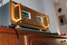
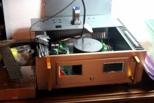

Superb build pics. I love the VU meters.Thanks Brian.
I sort of setup that SmugMug thing in a hurry. I'll fix it today.
Great stuff.
Superb build pics. I love the VU meters.
Great stuff.
Thank you man, I'd glad you think so. Old people have a lot of time on their hands. For awhile, at least.🙂 It's what I used to tell the wife during the pre-retirement years when she'd lament not having award winning flower beds like some of the neighbors. I'd always reply, "But Honey, they're home all day."
- Home
- Amplifiers
- Chip Amps
- Modulus-86 build thread