Most will probably be OK with a pair of reading glasses. The "OptiVisor" magnifying hoods are pretty decent. However, should you come across a dissecting microscope (4-10x magnification) on sale, definitely pick it up. A microscope with a good ring light makes SMD/SMT work a breeze.
I still solder my surf mount without visual aids other than my contact lenses but it is getting harder to read the markings on resistors and such.
Tom
I still solder my surf mount without visual aids other than my contact lenses but it is getting harder to read the markings on resistors and such.
Tom
Tom,
You obviously know this but you could preinstall the OPA1622 in an SMD reflow oven before selling the blank boards for example. That's what some fellas are doing with TI's TPS7A LDO regulators. Of course, you'll need a fab house for that (unless you have several $thousand around for a reflow oven). And I'm sure SMD fab houses have a minimum order...not the cheapest solution for small orders...
Best,
Anand.
Where there's a will there is a way. It is also possible to hand-solder those QFN packages, just don't expect 100 % yield. One of the guys I used to work with was running at about 80 % yield on 48-pin QFNs. Then we bought a $25k METCAL QFN/BGA reflow station.
The other side of the itty-bitty packages is that some of them require the use of micro vias and skinny trace/space design rules. Now you're talking some serious money for the PCB fab.
I think it'll take a while for audio to move out of the SOIC packages, so I'm not overly concerned.
You don't actually need fancy gear for reflow. Many are getting good results with toaster ovens. Some apply temperature control, many don't. Stencil the solder paste onto the board, place parts, bake. DING!!
Tom
Last edited:
It seems from the current trends that SMT will almost inevitably become the only available format...DIY audio is way too tiny to stand against that tide. Those of us in the geezer zone may need to hire/draft an eagle eyed steady handed youngster to aid in assembly. For me in my mid-60s the seeing part of the equation has been adequately addressed with an Optivisor with swing down loupe accessory. Unfortunately I have not found an analogous device to compensate for waning fine motor skills - with 2.5x lenses and a 2.5x loupe the tip of placing tweezers or a fine chisel soldering iron has a precision and accuracy about twice the size of the target component.
Using a soldering iron, would it be easier to use solder paste rather than solder wire for SMDs?
I'm going to start practising and would like to know which method to go with.
I'm going to start practising and would like to know which method to go with.
I've never tried solder paste with an iron as a heat source. I don't know how that would work, but its an interesting concept -- you can hold the part with a tweezers with one hand while using the iron with the other hand and not need a third hand for the solder wire. Still, I've been able to use iron and wire solder for all but the smallest ICs.
So, now that the HP1 project has matured, any update on ETA/pricing for the Mod286, and will it be SMT or old school for us 65+ yr olds with failing nearfied vision and shaky hands from running air powered sanders for the past 15yrs? 😱
Hum after adding THAT preamplifier
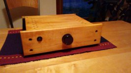
I have been very happy with my Mod 86 for the past couple of years. Recently, I added the THAT preamplifier and a potentiometer to the circuit, and put it in a box. Somewhere in the processs I introduced a low volume buzz into the sound from the speakers.
The buzz appears to be about 420 Hz (crudely measured with a smartphone app), is present when nothing is connected to the inputs, and increases in volume when the volume is raised.
The case is built from wood. Consequently, the potentiometer case is not grounded. Should it be?
The input wires from the RCA plugs at the back to the potentiometer and the THAT board are unshielded. I just twisted them together. Should I use dual conductor shielded cable?
Also, it may be that I got the connection from the THAT board to the Mod 86 wrong. I've connected them as follows: XLR pins 1 & 2 to V+ and V- on the Mod 86 and XLR pin 3 to GND on the Mod 86. Is this correct?
Any suggestions will be appreciated.
Attachments
I've connected them as follows: XLR pins 1 & 2 to V+ and V- on the Mod 86 and XLR pin 3 to GND on the Mod 86. Is this correct?
No it isn't: Pin 1 is chassis ground, Pin 2 +Signal and Pin 3 -Signal
Using a soldering iron, would it be easier to use solder paste rather than solder wire for SMDs?
I'm going to start practising and would like to know which method to go with.
I've used both. My first soldering of SMDs (20+ years ago) was with solder paste and a hot air pencil. I've used an iron with solder paste too. One big problem with solder paste is its very short shelf life. We used to refrigerate ours and it still wouldn't last a year.
Now all of our SMD soldering is with solder wire. Make sure everything is very clean (board, component, solder and iron tip) and use liquid flux liberally and you should do well with a little bit of practice. We use lead based (63/37) solder for all repair work. You can buy SMD practice boards to play with so you don't destroy a board you've payed lots for.
I don't bother with solder paste. It's useful for oven reflow. I generally find it to be a royal mess when trying to use a soldering iron. I use 0.5 mm diameter solder. Works great.
For XLR connections, Wikipedia comes to the rescue: https://en.wikipedia.org/wiki/XLR_connector#Three-pin_in_audio_use
Kevin has it right.
Also: Pin 1 on the XLR goes to Pin 1 on the MOD86. Pin 2 to pin 2. 3 to 3.
Tom
For XLR connections, Wikipedia comes to the rescue: https://en.wikipedia.org/wiki/XLR_connector#Three-pin_in_audio_use
Kevin has it right.
Also: Pin 1 on the XLR goes to Pin 1 on the MOD86. Pin 2 to pin 2. 3 to 3.
Tom
So, now that the HP1 project has matured, any update on ETA/pricing for the Mod286, and will it be SMT or old school for us 65+ yr olds with failing nearfied vision and shaky hands from running air powered sanders for the past 15yrs? 😱
I stand by my original estimate:
MOD286, bare board: $150; available by Christmas (this year). The final board revision will be Rev. 1.1.
For those interested in being early adopters on the MOD286, I do have the prototype boards (Rev. 1.0) available for $100 (Early Adopter Special). The Rev. 1.0 boards do not support parallel operation as that function required some tweaking. It will work flawlessly in stereo mode, though. Currently it comes with schematics, BOM, and a few pictures to guide assembly. It is very DIY that way.
I have a few boards (less than ten) left of the original stack. If you're interested in one, toss me an email through the Contact Us form on my website.
Tom
Hi Tom,
This is a great thread. Referring to post 2662, where you talk about Scott Wurcer. I have an edition of Radio Electronics dated in 1992 where Scott and a couple of guys "turbocharge" some LM1875 chips with opamps. They show about 4 schematics with various power ratings.
I think I have 2 LM3875 chips and 2 LM 4780 chips that I may try some of Scotts turbocharging design's (composite amps) , rather than trying to build just basic designs. I would call it a learning project, not just soldering components in place.
Was just wondering if you had run across this article in your travels????
Myles
Thanks much, kevin and tom, for pointing out the incorrect connection. After fixing the connection, the buzz is still there, though somewhat lower in volume. I tried to do another measurement of the frequency and it showed up as 65Hz this time.
Anything else I could try?
Anything else I could try?
Start by making a grounding plug. Take a regular male XLR cable connector and short pin 1,2,and 3 together. Plug that into the amp input and see if the hum goes away.
If the hum goes away when the input is shorted, the hum issue is further up the signal chain. If the hum remains, it's coming from within the amp.
Tom
If the hum goes away when the input is shorted, the hum issue is further up the signal chain. If the hum remains, it's coming from within the amp.
Tom
Thanks much, kevin and tom, for pointing out the incorrect connection. After fixing the connection, the buzz is still there, though somewhat lower in volume. I tried to do another measurement of the frequency and it showed up as 65Hz this time.
Anything else I could try?
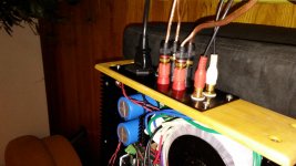
How about posting some close up pictures of your build, particularly the wiring.
Make 100% sure that you do not have cold solder joints of course.
What Tom said is also right on target in figuring out where the hum source is.
Thanks,
Anand.
This is a great thread. Referring to post 2662, where you talk about Scott Wurcer. I have an edition of Radio Electronics dated in 1992 where Scott and a couple of guys "turbocharge" some LM1875 chips with opamps. They show about 4 schematics with various power ratings.
Was just wondering if you had run across this article in your travels????
Yep. That was one of my main sources of inspiration for the Modulus-86. That article is a good place to start. You can find a link to it along with a few other useful links at the bottom of my Modulus-86 page. I strongly suggest that you set the circuit up in a simulator first. Learning by building is honourable, but in this case the lesson learned is likely going to be "composite amplifiers are difficult to get stable". Should you decide to give it a whirl and get stuck along the way, you can always start a composite amp thread here. I'll be happy to participate on such a thread to the extent that my time allows.
Tom
Tom,
Thanks for the tips. Sounds like I may have to learn a little more about Spice. The Electronics course I completed has a Circuit Logix program on the CD, which is based on Spice and XSpice. I will probably start with this, and then see what LT Spice offers if needed. I am in no hurry to build these as I have some other boards to populate first.
Myles
Still humming along
Thanks for the suggestion, Tom. Also, thanks, Anand. Based on the results, described below, I'm thinking the hum is outside the amp case, but I'm not sure how to get rid of it.
The stereo input to the case is supplied by a pair of RCA cables, shown in the photo.
The hum is present when these cables are disconnected.
It's also present when they are plugged in to the amp, but disconnected from the source (a TIVO, incidentally).
The hum is present when the cables are connected at both ends, but the character of the hum is different.
If I disconnect the RCA cables from the amp and short the female RCA inputs on the case, the hum disappears.
If I disconnect the RCA cables at the source (the TIVO) and short the two connectors of the cable, the hum disappears.
The TIVO has a two pin plug, not a three pin plug.
Hope this information leads to some ideas.
If the hum goes away when the input is shorted, the hum issue is further up the signal chain. If the hum remains, it's coming from within the amp.
Tom
Thanks for the suggestion, Tom. Also, thanks, Anand. Based on the results, described below, I'm thinking the hum is outside the amp case, but I'm not sure how to get rid of it.
The stereo input to the case is supplied by a pair of RCA cables, shown in the photo.
The hum is present when these cables are disconnected.
It's also present when they are plugged in to the amp, but disconnected from the source (a TIVO, incidentally).
The hum is present when the cables are connected at both ends, but the character of the hum is different.
If I disconnect the RCA cables from the amp and short the female RCA inputs on the case, the hum disappears.
If I disconnect the RCA cables at the source (the TIVO) and short the two connectors of the cable, the hum disappears.
The TIVO has a two pin plug, not a three pin plug.
Hope this information leads to some ideas.
Attachments
- Home
- Amplifiers
- Chip Amps
- Modulus-86 build thread