While shielded star-quad is good for long XLR cables in harsh electrical situations, coax is much better for RCA cables...........................................
I'm also a believer in star quad and use it for both RCA and XLR terminated ICs. I hadn't thought of using it for long speaker cables because I've only seen it in awg sizes usually associated with ICs. I have to see if it's available in 16 or 14 AWG. I need a pair of 20 foot long cables.
For speaker cables unshielded twisted quads are available or cables with two twisted pairs.
For speaker cables unshielded twisted quads are available or cables with two twisted pairs.
I don't see any advantage of using twisted pairs on the speaker connections. The output impedance of the amp is in the mΩ range. The load is 4-8 Ω. You'll have a hard time getting any electromagnetic signals to couple onto that.
What's more common with speaker cables is that they pick up RF. The twisted pairs won't help you there. 100 pF directly from the speaker connector to the chassis (short leads!) might help.
I've never needed any RF protection on the amps I've built. I'm thinking it's an issue if you live with a TV tower in your backyard or next to a HAM radio operator with a 1 kW transmitter and poor VSWR. In the latter case, you really need to get your neighbour to fix his rig.
Tom
Jim Brown has a different view-point. But then in addition to being an EMI/RFI expert, he is also a Ham radio operator.
"RFI, Ferrites, and Common Mode Chokes For Hams"
http://www.audiosystemsgroup.com/RFI-Ham.pdf
But twisting can be a free tweak.
"RFI, Ferrites, and Common Mode Chokes For Hams"
http://www.audiosystemsgroup.com/RFI-Ham.pdf
But twisting can be a free tweak.
Jim Brown has a different view-point. But then in addition to being an EMI/RFI expert, he is also a Ham radio operator.
"RFI, Ferrites, and Common Mode Chokes For Hams"
http://www.audiosystemsgroup.com/RFI-Ham.pdf
Good read with lots of good information and measurements. I'm curious for your thoughts on how it applies to the speaker outputs we were discussing.
But twisting can be a free tweak.
...which depending on the coupling mechanism may/may not make any difference at all.
Tom
I was replying to 'henrylrjr's more general cable statement.
As for interference, it always pop's up at the most inconvenient times.
Jim Brown was past AES co-chair of the EMI/RFI committee.
About 50 more of his papers and Power Points:
Audio Systems Group, Inc. Publications
As for interference, it always pop's up at the most inconvenient times.
Jim Brown was past AES co-chair of the EMI/RFI committee.
About 50 more of his papers and Power Points:
Audio Systems Group, Inc. Publications
Yeah, it's not especially hard to come up with cable measurements showing 20-40ish dB RF rejection from various combinations of twisting and shielding if one goes and looks. The assertion an amplifier's RF output impedance is low is questionable too. Even fairly capable integrated parts have impedances in the tens of ohms in the tens of MHz. Thiele networks are capable of hundreds of ohms in that range, though usually are closer to 10 ohms and the amp receives some rejection benefit since feedback's taken inside the Thiele. I'm also aware of plenty of oscilloscope probes and some faster headphone amps which readily pick up RF. Though, to be 100% fair, I've not looked at the can amps closely enough to determine how much of the measured RF came on the input versus getting into the control loop via the output.
The basic point still stands, though. As a class, audio power amplifiers generally are fine without taking any particular measures to reject RF coupled on the output. There are certain types of designs, all uncommon, where I'd be concerned about output coupled noise. The Mod, or indeed any of the amps I'm aware of Tom having built, isn't among them. So whilst availability of twisted speaker cables from honest manufacturers is reasonable, meaning predatory snake oil pricing isn't particularly a concern, I feel there remains some merit in noting it's a because one feels like it expense rather than a necessary one.
The basic point still stands, though. As a class, audio power amplifiers generally are fine without taking any particular measures to reject RF coupled on the output. There are certain types of designs, all uncommon, where I'd be concerned about output coupled noise. The Mod, or indeed any of the amps I'm aware of Tom having built, isn't among them. So whilst availability of twisted speaker cables from honest manufacturers is reasonable, meaning predatory snake oil pricing isn't particularly a concern, I feel there remains some merit in noting it's a because one feels like it expense rather than a necessary one.
The assertion an amplifier's RF output impedance is low is questionable too.
I didn't say anything about the RF output impedance. The mΩ output impedance I mentioned is within the audio range.
From Speedskater's comments about Starquad cables and microphone cables I figured he was concerned with mains hum coupling into the circuit. My basic point is that you'll be very hard pressed to couple anything into the MOD86 within the audio band.
I'm also aware of plenty of oscilloscope probes and some faster headphone amps which readily pick up RF. Though, to be 100% fair, I've not looked at the can amps closely enough to determine how much of the measured RF came on the input versus getting into the control loop via the output.
Yep. Been there. Done that. I pick up a few hundred mV of 88-108 MHz RF on the ground lead of my oscilloscope probes. That's why I mostly use my 400 MHz scope in 20 MHz mode. With wideband amps, such as some headphone amps, one has to be careful with this approach, though. It's easy to miss an RF oscillation in your amp when the bandwidth limiter is turned on on the oscilloscope. That's one of the reasons I picked up a 2.9 GHz spectrum analyzer when I had the chance. It works wonderfully to figure out if your amp has a spurious RF oscillation or if it's just picking up the local FM radio or TV station.
In case of the Modulus-86, the LM3886 is slow enough that RF oscillation isn't much of a concern. The LM3886 has a good handful of other quirks, but when properly fed and cared for it is very well behaved.
The basic point still stands, though. As a class, audio power amplifiers generally are fine without taking any particular measures to reject RF coupled on the output.
Yep.
Tom
What layout is better
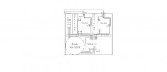
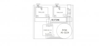
I've attached two layouts for my Parallel86 and would appreciate feedback.
One layout has a 12" heatsink, in the middle, running from side to side. It serves two purposes, one as a heatsink, the other as a brace to keep the thin aluminum bottom cover flat. My only hesitation is that the Power86 wires, connected to the left PBC, are parallel to and about 1 1/4" away from the right PCB speaker output wires. I don't know if that should be a concern.
The other layout is like my Mod86. Each PCB has it's own heatsink and it will have a brace, just like my Mod86, to keep the bottom cover flat. I like this layout because, the Power86 wires are on one side of the PCBs so, no power wires are near any of the signal input or output wires.
Bottom line is, if power wires and speaker output wires being parallel and 1 1/4" apart is not a concern, I will probably build the one with the 12" heatsink. It's thermal resistance, at C/W/4.5", is .702. The 5 3/8" heatsink, at C/W/4.5", is .949.
Thanks,
henrylrjr
Attachments
Honestly, they're functionally identical. One could argue that the arrangement with two heat sinks allows for shorter supply wiring (which doesn't matter greatly due to the Parallel-86's high power supply rejection ratio) and shorter speaker out wiring (which doesn't matter greatly as you follow that few inches inside the chassis with several feet of wire to the speaker).
The arrangement with the one large heat sink saves you the bottom brace and you could potentially use a larger (wider) heat sink, allowing the amps to run cooler. The drawback of this arrangement is that you run the wires over the heat sink. You'll need to devise some gizmo to prevent them from chafing.
The arrangement with two smaller heat sinks is cleaner from a wiring stand point. With the two heat sinks you have, using two sinks should result in better thermals (according to the thermal resistances you provide), though, I strongly suspect the two will be equivalent in thermal performance once you take into account the two heat sources vs one on one heat sink vs two.
In the end, the two are about the same. You say tomato. I say tomato. 🙂
Tom
PS: I'm not personally a fan of putting the transformer in the corner. I prefer a centred location. It results in fewer surprises and fewer bruised toes when you go to move the amp.
Last edited:
Henry,
take the transformer's shield wire direct to chassis floor using a short wire.
6A mains fuse seems very high for a 110/120Vac supply into a pair of chipamps.
I see the transformer has 4 primary taps for a dual primary type.
Each primary has a Flow and Return (Live and Neutral). This pair must be twisted. The other primary should similarly used a twisted Flow and Return pair.
The secondary outputs are also 4 wires. These too should be arranged as two pairs, each pair being the Flow and return of one secondary.
All the loop areas at the terminations of the transformer's pairs should be kept small.
All the above is to minimise the emi emitted by the transformer and it's wiring.
The +ve, -ve and Zero Volts from the PSU to each amplifier should be arranged as a twisted triplet. Again the loop areas at the terminations should be kept small to minimise emi.
The input XLR has 3 pins and a shell. The shell and pin1 are connected directly to the Chassis at the entry hole. Pins 2 and 3 are your signal and these are taken to the amplifier using a twisted pair. It can be screened or unscreened. If screened then it is better to connect both ends of the screen to the chassis using low impedance connections at both ends. A long pig-tail is not as good.
Finally each speaker pair should be twisted and incorporate low loop area terminations.
Attending to these emi minimisation steps will virtually remove the need to be concerned about emi effects of nearby cable pairs affecting any other cable pairs.
Last edited:
Honestly, they're functionally identical.
The arrangement with the one large heat sink saves you the bottom brace
The arrangement with two smaller heat sinks is cleaner from a wiring stand point.
Using two sinks should result in better thermals (according to the thermal resistances you provide), though, I strongly suspect the two will be equivalent in thermal performance once you take into account the two heat sources vs one on one heat sink vs two.
In the end, the two are about the same. You say tomato. I say tomato. 🙂
Tom
PS: I'm not personally a fan of putting the transformer in the corner.
Thanks Tom,
I bought a 3ft long piece for the original brace and already cut a second piece that will fit perfectly..just need to drill three holes.
I do like the cleaner wiring.
Even thought the 12" heatsink resistance is quite a bit lower than the 5 3/8" heatsink, it will be effectively higher with two chips on it, so I think either would provide sufficient cooling.
The transformer in the corner helps keep the bottom cover from sagging. So, based on my Mod86, no other bracing is required. My other amps weight from 40 to 80 lbs, are heavier on one side or front vs back, and I never had a problem moving them.
Thanks,
henry
Tom do you have any recommendations for clips/clamps for mounting the parallel86 to the heatsink. I'd prefer to use a simple bolted spring plate if possible.
Henry,
take the transformer's shield wire direct to chassis floor using a short wire.
6A mains fuse seems very high
The input XLR has 3 pins and a shell. The shell and pin1 are connected directly to the Chassis at the entry hole.
Thanks for the reply.I connected the shield wire as shown in Tom's Doc and everything works great. Why connect it differently?
What amp fuse would you suggest?
All wires will be twisted or bundled into appropriate groups. The schematic is intended to just show what connects where.
It's hard to see in the schematic but the shield is connected to pin1 and pin1 is connected, with a 1/16" long piece of wire, to the XLR body. The XLR body is connected to the back panel at the entrance hole. The back panel is connected to ground.
6A mains fuse seems very high for a 110/120Vac supply into a pair of chipamps.
That's very interesting given that the 6 A is dialled back from one of your previous recommendations.
With the 400 VA transformer, your recommendation of 2 - 3 * VA/Vmains results in an 8 - 12 A fuse.
This pair must be twisted. The other primary should similarly used a twisted Flow and Return pair.
The secondary outputs are also 4 wires. These too should be arranged as two pairs, each pair being the Flow and return of one secondary.
They should be tightly coupled. That doesn't necessarily mean twisted. Many transformer manufacturers, Electra-Print being one of them, actually advise against twisting the wires together.
The +ve, -ve and Zero Volts from the PSU to each amplifier should be arranged as a twisted triplet. Again the loop areas at the terminations should be kept small to minimise emi.
Again: They should be tightly coupled. In particular with heavy gauge wire, you usually end up creating a larger loop area than you would just bundling the wires tightly with wire ties.
The input XLR has 3 pins and a shell. The shell and pin1 are connected directly to the Chassis at the entry hole. Pins 2 and 3 are your signal and these are taken to the amplifier using a twisted pair.
That's actually very bad advice in case of the Modulus-86. If you want Pin 1 connected to the chassis at the entry, connect it there and continue the shield to the Modulus-86 board.
Finally each speaker pair should be twisted and incorporate low loop area terminations.
*tightly coupled.
Attending to these emi minimisation steps will virtually remove the need to be concerned about emi effects of nearby cable pairs affecting any other cable pairs.
Henry has already completed a Modulus-86 build successfully. It works as designed and he has no issues with it. Undoubtedly you noticed his build pictures a while back as you participated on the thread at the time. I'm curious why you choose to inject your advice here. Henry is clearly on the right track and all you're basing your advice on this time is the lack of drawn twists on wires in a schematic drawing.
Tom
Tom do you have any recommendations for clips/clamps for mounting the parallel86 to the heatsink. I'd prefer to use a simple bolted spring plate if possible.
Aavid P/N MAX08NG (Mouser 532-MAXCLIP08G) works well.
Thanks for the reply.I connected the shield wire as shown in Tom's Doc and everything works great. Why connect it differently?
Because the AES48-2005 standard says so. So it was written and so it shalt be done. No independent thinking allowed. 😉
The trouble with connecting only pin 2 and 3 to the Modulus-86 board is that it disconnects the RF input filter. If you want to be fully AES48-2005 compliant, you'll desolder the RF filter (three caps) from the board and move them to the XLR connector. Then terminate the filter there and only bring pins 2,3 to the board.
If I was designing a commercial product, I would put the XLR connector on the PCB and place the RF filter right at the XLR connector. However, the Modulus-86 and Parallel-86 are DIY boards. I chose to deviate from the AES48 standard as walking people through soldering the components onto the back of an XLR connector was a support headache I'd rather not have.
In your situation, I recommend connecting everything as shown in the design documentation - just as you did on your Modulus-86 build.
It's hard to see in the schematic but the shield is connected to pin1 and pin1 is connected, with a 1/16" long piece of wire, to the XLR body. The XLR body is connected to the back panel at the entrance hole. The back panel is connected to ground.
That's what you want.
Tom
Last edited:
Just to be clear for anyone interested. The XLRs I bought have a small tab, which is essentially part of the body, right next to pin1.
The length of the wire from pin1 to the tab, after soldering and trimming, is about 1/16". The tab is so close to pin1 that I was actually considering bending the tab, such that it would be in contact with the outer surface of pin1, and applying a bit of solder. I choose not to bend it and use it as designed.
Regarding twist vs bundle, with Tom's input I chose to bundle wires. The only wires I would have twisted would have been those from the PCB speaker connections to the binding posts. However, in my build, the wires were only about 1 1/4" long so twisting wasn't in the cards.The final pic is in post 2374.
You did very well in your Modulus-86 build. Do the same for the Parallel-86 build and you'll achieve the same stellar results.
Tom
Tom
You have taken this completely out of context.That's very interesting given that the 6 A is dialled back from one of your previous recommendations.
With the 400 VA transformer, your recommendation of 2 - 3 * VA/Vmains results in an 8 - 12 A fuse.
.............
A close rated fuse is VA/Vac.
A fuse that is big enough to not suffer nuisance blowing in starting an inductive load is 3times bigger.
I always recommend a close rated fuse. And that requires a soft start.
400VA/115Vac gives a close rated fuse of less than, or equal to, 3.47A. Therefore use a T3.1A fuse with a 18r or so soft start current limiting resistor that should give reliable repeated cold starts.
As I said, 6A seems too big for a 110/120Vac supply for a pair of chipamps.
Last edited:
Because he asked........................ I'm curious why you choose to inject your advice here. Henry is clearly on the right track and all you're basing your advice on this time is the lack of drawn twists on wires in a schematic drawing.............
You have taken this completely out of context.
That's entirely possible. I am a mere human... 🙂
A close rated fuse is VA/Vac.
A fuse that is big enough to not suffer nuisance blowing in starting an inductive load is 3times bigger.
Thank you for clarifying. That's very useful information.
Because he asked.
Maybe I misinterpreted your response, but you came across as someone who assumed Henry had no experience at all. While he isn't the most experienced here, and he's usually the first to admit this, he does have a successful build behind him. He should at least receive that much credit.
Tom
- Home
- Amplifiers
- Chip Amps
- Modulus-86 build thread