I wasn't thinking about the speakon to speakon connections. I was thinking about potential problems resulting from stranded copper wires, oxidizing over time, inside the amp. For example, connections between terminal blocks. An example would be PWR86 J2 to Mod86 J3 and Mod86 J1 to internal speakon connections. Basically the internal wiring.
Last edited:
Did the thread get too far on-topic? Sincere apologies... 🙂 
Like you said: The wiring in your 116 year-old house still works. I wouldn't worry about the wires oxidizing. Just because the surface layer of molecules have turned to oxide doesn't mean that the oxidation will continue until there's no wire left. Many metal oxides are really quite inert so once the surface layer of the wire has oxidized, no further reaction happens.
Tom
I'll consider the THAT driver. It may be something I add later.I suggest adding at least a buffer to that. I know some fancy "passive preamps" (= input selector + volume control) but it's really not a good solution from a technical perspective. The variable (and usually highish) output impedance is not a good solution. It sounds like if you add one of my THAT Drivers to what you already have, you'll have a good preamp to drive a Modulus-86.
This doesn't quite fit my needs. I'm looking for a rotary to actually switch between inputs. This selector doesn't do that. It provides an output which then informs a set of relays on what switching to do.As Anand said above, my Selector x4 will do the job. It will also provide you with a nice visual indication of which output is selected. The LED of the selected input glows brightly while the un-selected input LEDs glow only subtly. Fun with LEDs... 🙂 The Selector x4 provides signals out that you can use to drive relays for input selection.
This doesn't quite fit my needs. I'm looking for a rotary to actually switch between inputs. This selector doesn't do that. It provides an output which then informs a set of relays on what switching to do.
In that case you either need to find a relay board somewhere or you're back to the Lorlin/CK/Grayhill/Elna style of rotary switch. You may have to get used to the pine cone of wiring.
Tom
Tom, I assume this will be fine for the inductor on the zobel?
EPCOS B82132A5402M Axial Leaded High Frequency Inductor, VHF Choke, B82132 Series, 2 µH, ± 20%, 0.02 ohm, 4 A, 186 MHz
EPCOS B82132A5402M Axial Leaded High Frequency Inductor, VHF Choke, B82132 Series, 2 µH, ± 20%, 0.02 ohm, 4 A, 186 MHz
Tom, I assume this will be fine for the inductor on the zobel?
Not if you want low THD. The Thiele inductor needs to be an air core inductor. The core causes quite a bit of distortion (>0.1 % at 20 kHz).
I strongly recommend just winding the inductor as I show in the design doc. It's pretty easy to do and with a little practice it takes about 5-10 minutes.
Tom
I built a Mod86 and am about to build a Parallel86 and was concerned about copper wire oxidation.
In an earlier post I asked about the effect of oxidation of copper stranded wire and skin effect as it relates to music.
I got a response saying that skin effect is related to RF or high frequency signals and has no bearing on the audible range we listen to for music.
If that's true why bother with cramolin or Caig products? Why try to make gas tight fittings. Our car, battery acid excluded, and household wiring seem to work for for years. My house wiring is 116 years old and all the lights works.
All the hype seems to be snake oil. Am I missing something?
I do NOT use Caig to address corrosion between individual wires in a cable. I DO use Caig for contact to contact interfaces (i.e., RCA plug toRVA socket), or wire to contact interfaces (i.e., wire to binding post or push-on terminal). My own personal experience is that skin effect is not relevant (i.e., audible) for simple audio signals. Therefore, I ignore most advertisements for cable and wire touting special twisting and winding techniques.
As far as house wiring, the simple answer is that house wiring is not used to conduct audio signals. Therefore, contact resistance at terminals of a switch or light fixture are usually not an issue.
skin effect
I use caig stuff as you do and also have never done anything to individual wires in a cable. However, I've seen old clear plastic Monster cables where the whole length of wire is oxidized. I imagine that happens, over time, to most cables.
I also noticed that short exposed lengths of wire, between the ends of cable jacket and terminal, on almost all my cables have oxidized. Having heard of skin effect, and read too many conflicting posts and snake oil ads, I thought oxidation was bad for sonics.
Believing oxidation was bad, I started using teflon coated silver plated copper wire. Fairly cheap on ebay but a real pain to strip.
I've read many posts here and a few documents on skin effect and now believe it doesn't affect audio signals. I'm back to using inexpensive stranded copper wire.
Is it also hogwash that PVC is bad and teflon is best. Some Hi-End sites even sell pure cotton jacketing and go so far as to say unbleached is better than bleached. Seems the only thing not for sale is unobtainium.
Thanks,
henry
I use caig stuff as you do and also have never done anything to individual wires in a cable.
Where oxidation matters is at the terminations - i.e. where the wires enter connectors and terminal blocks. You want a good gas tight connection there. The various manufacturers of terminal blocks know this already and have designed their products accordingly.
If using the Caig stuff makes you sleep better at night, go for it.
However, I've seen old clear plastic Monster cables where the whole length of wire is oxidized. I imagine that happens, over time, to most cables.
I remember those. As I recalled, the chloride in the PVC jacket somehow ended up oxidizing the copper wire resulting in some brownish-green copper oxide. The oxide is harmless but doesn't look pretty behind the clear PVC jacket. It also made it clear that the cables weren't "oxygen free" as advertised. There was a lawsuit and Monster had to drink their own snake oil.
Having heard of skin effect, and read too many conflicting posts and snake oil ads, I thought oxidation was bad for sonics.
The common misconception is that skin effect causes the current to only flow in the outermost layer of conductive atoms of a wire. That is true at infinite frequency (way beyond the visible spectrum), but is most certainly not true at DC. Audio is pretty darn close to DC.
What happens is that the alternating current in the wire sets up eddy currents. These eddies cause the distribution of electrons in the wire to change from uniform at DC to a Gaussian (or Gaussian-like) distribution. The current density in the centre of the wire is lower than the current density near the outer edge of the wire. 63 % of the current now flows within one skin depth from the surface of the wire. 98 % flows within four skin depths of the surface. Both of these numbers assume a wire with infinite diameter.
The skin depth in copper is 0.5 mm at 20 kHz. The percentages above would then indicate that you should start worrying about skin effect when the wire exceeds eight skin depths (4 mm in diameter). That's 13 mm2 (AWG 6) for 20 kHz signals.
Rather than relying on ads for your understanding, I suggest grabbing a textbook or reading the article on skin effect on Wikipedia: Wikipedia - Skin Effect
This skin depth calculator will save you some work if you're curious about the skin depth at various frequencies: Skin Depth Calculator.
I've read many posts here and a few documents on skin effect and now believe it doesn't affect audio signals. I'm back to using inexpensive stranded copper wire.
Good for you. As you can see from the previous paragraph, I wholeheartedly agree with you on that.
Is it also hogwash that PVC is bad and teflon is best. Some Hi-End sites even sell pure cotton jacketing and go so far as to say unbleached is better than bleached. Seems the only thing not for sale is unobtainium.
LOL. I think this is one of the best reality checks I've seen from you.
Tom
I have things like lamps at home with 'zip cord' for power leads made with clear (PVC?) insulation and they haven't turned green. But I've also seen wires/cords that have -- who knows about he non-clear ones? ;-)
For wiring inside a chassis, as someone above already commented, I prefer Teflon-insulated wire if I can get it mainly because I don't have to worry about it melting and pulling back. It often seems that I need to apply more head to the connection for longer than I want (due to not having enough hands or large thermal mass of connector, etc.) and normal insulation suffers. It's largely an aesthetic/taste thing, but if I can get it, I use teflon. I doubt that it has any 'sonic' benefit. The biggest 'benefit' other than the melting issue is to impress other audiophiles with the quality of your build, of course not mentioning to them that in the same chassis I might have used a piece of doorbell wire from the local home improvement big box store.
One type of audio cable that is NOT snake oil is the 'Star-Quad' mic and speaker cable from Canare (and others). See wikipedia article on 'star quad cable'. This is of benefit in long mic/line cable runs as well as longer speaker cable runs. The benefits are minimal, at best, for audio system cables and of no import for wiring within a chassis.
Yes, teflon is more difficult to strip without nicking wires. One must use care. I usually use an x-acto knife carefully. If I use a wire stripping tool, I generally try to use the hole for one wire size larger than I am stripping .
Last edited:
Um, frequency dependence of RLCG parameters is due to the loop of lowest impedance increasingly being the loop of lowest inductance. R increases (skin effect), L decreases, C increases, and (to a limited degree) G increases because the field distribution shifts from more or less uniform volume conduction at low frequencies to conduction on the surfaces closest to each other at high frequency. The rest of the analysis is in the right direction but somewhat overestimates cable sizing, I think because the conceptual model of the field distribution used is a bit generous (it's not an eddy current phenomenon).What happens is that the alternating current in the wire sets up eddy currents.
However, it doesn't matter. Resistance in typical speaker cables increases by low single digits mOhm/m from DC to 20kHz due to skin effect. This is comparable to perhaps 30nH/m, relatively minor compared to the 200-400nH/m typical of speaker cables. With the 2-3 meter cable runs of home audio the limiting factor on the Mod's damping factor from a few kHz up is thus the Thiele inductor. All in all, skin effect related error at the driver ends up 40 to 50dB down compared to total impedance related error. I'd rate that about -25dB GF.
For wiring inside a chassis, as someone above already commented, I prefer Teflon-insulated wire if I can get it mainly because I don't have to worry about it melting and pulling back.
One type of audio cable that is NOT snake oil is the 'Star-Quad' mic and speaker cable from Canare (and others). This is of benefit in long mic/line cable runs as well as longer speaker cable runs.
Yes, teflon is more difficult to strip without nicking wires.
I also ran into the problem of PVC and some other jackets shrinking and pulling back. Lately I've been heavily tinning the large mass connectors and tinning the wires. The joint can then be made pretty quickly and jacket melt back is very minimal.
When doing this I hold the large mass tinned connector in a small vise and the tinned wire in a third hand clip. I position the wire such that it is pushing down against the tinning on the connector. I hold the soldering tip against both the tinned wire and tinning on the connector. When the solder melts the wire sinks such that it is probably in contact with the connector and I add a tad more rosin filled solder. So far the joints end up very shiny and work well. I'm using 6347 leaded solder. Is this a bad practice?
I'm also a believer in star quad and use it for both RCA and XLR terminated ICs. I hadn't thought of using it for long speaker cables because I've only seen it in awg sizes usually associated with ICs. I have to see if it's available in 16 or 14 AWG. I need a pair of 20 foot long cables.
With the 2-3 meter cable runs of home audio the limiting factor on the Mod's damping factor from a few kHz up is thus the Thiele inductor. All in all, skin effect related error at the driver ends up 40 to 50dB down compared to total impedance related error. I'd rate that about -25dB GF.
Exactly. Definitely in the Gnat Fart range of things.
Tom
... snip ...
I suggest adding at least a buffer to that. I know some fancy "passive preamps" (= input selector + volume control) but it's really not a good solution from a technical perspective. The variable (and usually highish) output impedance is not a good solution. It sounds like if you add one of my THAT Drivers to what you already have, you'll have a good preamp to drive a Modulus-86.
... snip ...
Tom
Tom, Can you (or someone) expand on that a bit? Currently, I'm using a relay based attenuator from Elma in a "passive pre-amp" capacity for my Mod86. Input impedance is not bad at ~10k throughout the range, but I'm sure the output impedance varies substantially over the range. I'm running 2 of the Relay Attenuator boards for balanced-in-balanced-out operation.
Would I be better off with an active buffer stage on the output of the relay attenuator? (THAT Driver(s) for instance?)
Thanks in advance!
Oh, and how about adding Multiple OUTPUT switching to that Pre-Amp of yours?
Last edited:
In a "passive preamp" (aka volume pot) both the input and output impedance vary:
Rin = Rtop + Rbottom||Rload
Rout = (Rtop + Rsource)||Rbottom
Usually Rload >> (Rtop + Rbottom), thus Rin = (Rtop + Rbottom) = Rot.
Rtop and Rbottom are the resistances of the top and bottom halves of the volume pot, respectively, split in the middle by the wiper.
Usually Rpot is in the range of 10 kΩ to 100 kΩ, thus the output impedance is pretty high. This goes into a high-impedance input of a power amp. So you're routing a relatively high-impedance node between two chassis. From an EMI/RFI perspective that's not a good solution.
Add an output buffer to the pot and the output impedance of your amp becomes low (within the bandwidth of the buffer anyway) and constant (within the limitations of the loop gain of the buffer amp). This makes it harder to couple interference signals onto the interconnect.
Tom
With a 100K pot you can start to run into problems with high frequency roll off due to the capacitance in your interconnects. You can find a useful calculator here: Cable Calculator
Putting the volume pot into the power amp means the load impedance seen by the pot is known and the wire run is limited. This allows for actual circuit design and layout to be performed to ensure good performance. So, yes, that's a good way to go.
Tom
Tom
I've posted about building an A B speaker selector switch and included some sketches.
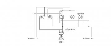
This is an update on my A and B selector switch in the Parallel86 chassis. It eliminates the need for, a separate box, four Speakon connectors and reduces the number of connections.
I’ve attached a new schematic of how I think a DPDT speaker selector switch, inside the Parallel86 chassis, should be wired.
Since there are left and right channel PCBs, and left and right channel speakers, the schematic shows both A and B left channel speaker negatives (-) connected to the left channel PCB GND at the terminal block. The same is shown for the right channel.
Is that negative wiring scheme important or can the speaker negatives return to either PCB?
I ask because I wonder if both left and right PCB speaker GNDs are ultimately going back to the same GND.
I also imagine the schematic could be simpler but I believe it shows needed connections. Am I missing anything? Is it totally wrong?
Thanks,
henry
Attachments
Is that negative wiring scheme important or can the speaker negatives return to either PCB?
The way you have it drawn is correct.
The returns from the right speakers should go to the right channel Parallel-86 PCB. Left speaker return to the left PCB. Exactly like you have it drawn.
Tom
- Home
- Amplifiers
- Chip Amps
- Modulus-86 build thread