Anyone going to Burning Amp? You'll find me in Siegfried Linkwitz & Nelson Pass' "LX Room". My Modulus-686 amp will be used to power a pair of LXmini+sub.
https://www.magiclx521.com/epages/17940394.sf/en_GB/?ViewObjectPath=/Shops/17940394/Categories/news
Tom
That's quite something Tom, an implicit seal of approval from NP. Not that I needed anyone to tell me how good your amps sound!
I certainly appreciated the nod. As I understand it, NP was considering powering the speakers with his ACA, but concluded that more power was needed. In his JFET-based LXmini XO document, he mentions that he and SL decided on 80 W as the minimum power required for the LXmini.
Tom
Tom
Ha...
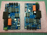
After finishing the two Power686 a few days back, tonight I completed the two ISSs (int. space stations;-) ). Plugged it in with my bulb protector and bingo, both are working perfectly. Tom big compliment - you just make it easy and error proof.
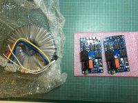
Today also the two 800VAs arrived and I hooked em up too for an ISS test. All good. Man those things are big and heavy🙂. See some pics below of the beauties.
After finishing the two Power686 a few days back, tonight I completed the two ISSs (int. space stations;-) ). Plugged it in with my bulb protector and bingo, both are working perfectly. Tom big compliment - you just make it easy and error proof.
Today also the two 800VAs arrived and I hooked em up too for an ISS test. All good. Man those things are big and heavy🙂. See some pics below of the beauties.
Attachments
Tom big compliment - you just make it easy and error proof.
Thank you. I'm glad everything came together nicely for you.
See some pics below of the beauties.
Holy crap! That's what I call a transformer!
I love how the (probably pretty stout) primary leads look itty-bitty compared to everything else. I'm guessing it's a 230 VAC, single primary. If yes, you connect it to terminals 1 and 4 on the output of the ISS.
Tom
Thank you. I'm glad everything came together nicely for you.
Holy crap! That's what I call a transformer!
I love how the (probably pretty stout) primary leads look itty-bitty compared to everything else. I'm guessing it's a 230 VAC, single primary. If yes, you connect it to terminals 1 and 4 on the output of the ISS.
Tom
Yep that’s what I thought too when I unwrapped it today - and there are two of them It is indeed a 230V single primary but thanks for the hint. I already connected it for testing.
Yes the secondaries are so unwieldy they keep the Power686 suspended in mid air once it is hooked up. I guess I need some hefty tools for final assembly.
Why the 800VA, 25V (Amplifon) you may justifiably ask. Well, the costs difference vs the 500va was some 40EUR however given the overall cost of ca. 1900 EUR for the entire project (2 monoblocks) the difference started to appear small. And of course it delivers the 16A the 686 can maximally cope with ;-) (but not my speakers yet;-)))
Wish me luck.
Last edited:
Yes the secondaries are so unwieldy they keep the Power686 suspended in mid air once it is hooked up. I guess I need some hefty tools for final assembly.
Heh. That reminds me of an E-I core transformer I had at one point. 24 V @ 50 A. The secondary was a copper band that was about 8x3 mm in cross section. There was no bending that.
Why the 800VA, 25V (Amplifon) you may justifiably ask. Well, the costs difference vs the 500va was some 40EUR however given the overall cost of ca. 1900 EUR for the entire project (2 monoblocks) the difference started to appear small.
Go big or go home!
And of course it delivers the 16A the 686 can maximally cope with ;-)
Actually, the MOD686 can deliver 21 A peak if your supply can keep up. It makes you wonder exactly where the line is between an amplifier and a welder. 🙂
7 A per LM3886. You probably got the 16 A figure from the current limit on the Mean Well SE-600-36 that I used for testing.
Tom
Oh shoot. I should have gotten the 1000VA ;-))
Just kidding.
I incorrectly deduced the 16A from the manual- page 5, where it said ... the power supply should have between 10-16A for 4ohm operation. I guess the 16a from the 800va trafo are rms so peak should be 22a?
Either way... plenty of juice.
Just kidding.
I incorrectly deduced the 16A from the manual- page 5, where it said ... the power supply should have between 10-16A for 4ohm operation. I guess the 16a from the 800va trafo are rms so peak should be 22a?
Either way... plenty of juice.
Tom,
I see C11,C18 are rated for 16V and they are used for singal copuling between Opa1642 and Lme49724. The dac I built has transformer on the output, so no way for DC to show up. In such case could I actually short C11 and C18?
Thanks,
I see C11,C18 are rated for 16V and they are used for singal copuling between Opa1642 and Lme49724. The dac I built has transformer on the output, so no way for DC to show up. In such case could I actually short C11 and C18?
Thanks,
Has someone been able to properly test their Guardian 686’s?
When i supply 25v to the power supply connector i measure no voltage at all across R1 and R5, not even after having waited for a minute.
The weird thing is that it is consistent on both my guardian 686’s..
When i supply 25v to the power supply connector i measure no voltage at all across R1 and R5, not even after having waited for a minute.
The weird thing is that it is consistent on both my guardian 686’s..
Pardon my belated response. I'm on vacation and only have intermittent access to the internet.
You'll need power connected to both power supply connectors, both 8-pin ICs installed, and the appropriate (SD, GND) jumpers installed for the circuit to work.
The circuit which drives the LEDs in the photovoltaic gate driver ICs is a simple RC with a bipolar transistor detecting the voltage and turning on the LED. If you have all the components installed correctly, there isn't much to to go wrong there.
Tom
Hi Tom,
You're delivering beyond what we all expect from you when you are on vacation 😀 So thanks a lot for being so involved with your builders.
Like we already discussed via email i've found out I need to power both halves 🙂 Will do final testing the coming week.
And then it is time to assemble everything together, i'll put some pictures of the end result here on the forum.
TomPardon my belated response. I'm on vacation and only have intermittent access to the internet.
You'll need power connected to both power supply connectors, both 8-pin ICs installed, and the appropriate (SD, GND) jumpers installed for the circuit to work.
The circuit which drives the LEDs in the photovoltaic gate driver ICs is a simple RC with a bipolar transistor detecting the voltage and turning on the LED. If you have all the components installed correctly, there isn't much to to go wrong there.
Tom
Just r relaxxxxx!!!!!!!
Yeah... I need to learn to relax. 🙂
I was camped out at Neah Bay, WA (USA) the past couple of nights. No internet. Got the campfire going. That was a good time. I find that relaxation is more likely to happen when I don't have internet access.
Tom
I was camped out at Neah Bay, WA (USA) the past couple of nights. No internet. Got the campfire going. That was a good time. I find that relaxation is more likely to happen when I don't have internet access.
Tom
Thanks...
Cool switch ... even vandal-proof, for those vandals at home ;-).... btw are you sure about the LED in the Switch not being polarized or am I just reading the spec incorrectly. There is a version e.g. PV6F24011-3G1, which offers a two pin red/green led in anti-parallel configuration (see attachments) - wouldn´t that connect directly to the ISS LED connector and still provide the desired functionality (standby red, on green)?
Thx.
I was on vacation, so work stalled somewhat on the Mod686 Monos. Meanwhile the above (see post #571) mention PV6F Switches came in.
BTW. They work perfectly with Tom´s ISS (Softstart) - the green led ring of the switch is on, when in standby and it turns into red when on. I hooked em up just as in the spec sheet.
Last edited:
BTW. They work perfectly with Tom´s ISS (Softstart) - the green led ring of the switch is on, when in standby and it turns into red when on. I hooked em up just as in the spec sheet.
Very cool! Should you wish to have the colours reversed, you can always swap the wires to the LED.
Tom
Last edited:
Couple of pics from my build 🙂
modulus_686_before_final_assembly.jpg - Google Drive
modulus_686_assembled.jpg - Google Drive
modulus_686_up_and_running.jpg - Google Drive
Tom. This amp is amazing! Thank you!
modulus_686_before_final_assembly.jpg - Google Drive
modulus_686_assembled.jpg - Google Drive
modulus_686_up_and_running.jpg - Google Drive
Tom. This amp is amazing! Thank you!
Couple of pics from my build 🙂
modulus_686_before_final_assembly.jpg - Google Drive
modulus_686_assembled.jpg - Google Drive
modulus_686_up_and_running.jpg - Google Drive
Tom. This amp is amazing! Thank you!
Nice! I love the Toroidy transformer, super quiet! Big 400mm deep chassis, very nice!
Enjoy the fruits of your labor!
Best,
Anand.
Well, maybe not building one disqualifies me from posting much here , but I was lucky enough to spend a couple of days with Tom and his own personal build of this
new piece.
I highly recommend both- perhaps might be more power than I need for my upstairs background system, but I guess I can live with it until passed on to next lap of its current road trip - the amp, I mean
new piece.
I highly recommend both- perhaps might be more power than I need for my upstairs background system, but I guess I can live with it until passed on to next lap of its current road trip - the amp, I mean
Last edited:
Couple of pics from my build 🙂
modulus_686_before_final_assembly.jpg - Google Drive
modulus_686_assembled.jpg - Google Drive
modulus_686_up_and_running.jpg - Google Drive
Tom. This amp is amazing! Thank you!
Cool. Thanks for sharing. Especially the room saving way you mounted the 686 boards. Did you bent the LM3886 contacts? Do you have a detailed photo of the LM3886 soldered to the board? Thx.
BTW. After my second vacation and now that the Modushop guys are back from theirs I have finished the CAD drawing for the cutouts and will order the housings tonight.
Well, maybe not building one disqualifies me from posting much here , but I was lucky enough to spend a couple of days with Tom and his own personal build of this
new piece.
I highly recommend both- perhaps might be more power than I need for my upstairs background system, but I guess I can live with it until passed on to next lap of its current road trip - the amp, I mean
What were your specific impressions of the 686 and what was the listening setup?
- Home
- Vendor's Bazaar
- Modulus-686: 380W (4Ω); 220W (8Ω) Balanced Composite Power Amp with extremely low THD