Thanks for posting this Phill - I was planning to post something similar. I'm having extensive work on my kitchen so my time/attention keeps being diverted to that project.
shift to i2c for control:
an alternative to moving the GPIO expanders to the peripheral boards is to design a small module to hold an expander. This would then be a 'i2c to relay' board where 2 or more could be chained. But I suppose the only reason to do this would be if you were concerned with having (noisy?) digital signals on an audio board, eg. the volume board. If this is not an issue then I see no problem with the expanders on the peripheral board.
changing power supply.
Is there an argument for having a separate power supply module that can be controlled from the MCU? I can see that it's not as simple as that as there still needs to be power to the MCU so that it can listen for the 'on' button on the remote control or encoder buttons and then bring everything out of sleep.
The Atmega can easily control a 16x2 or 20x4 LCD (or alphanumeric OLED display) so I agree with your proposed Basic Control Board. As the main requirement is to display the input source and the volume level, many DIYers will be quite content with that solution.
"Buy one to turn the knobs/switches, the other to paint the display."
The benefit of a modular design is that this is clearly an option that one of you could implement. Indeed, as the control boards are now fairly simple, it would be possible to put two of them in the same chassis and implement some communication between them. The only constraint that that puts on the design of the control board is that relevant (or all unused) MCU pins are taken to a footprint on the PCB where a header (or headers) could be soldered to give future developers the flexibility to implement new ideas. It might increase the size of the control board a little but the cost/price would be the same.
If you want to stick with having latching relays on your input board, you could add a 'mute' relay that grounds the outputs (the following power amp might prefer its inputs grounded rather than left floating when the preamp goes to sleep). Alternatively, you could signal the volume board to go to zero volume as you go to sleep - this only works if zero volume means just that, which could be the case with a relay based volume board. (This doesn't protect against someone just unplugging the preamp though).
Geoff
exactly, the right way
"Right" is very subjective. For me, this is a "when all you have is a hammer, everything looks like a nail" issue. The ATMega is a great MCU, I don't dispute that. But for me, it's simply not the right tool for the job. If you want to drive a complex OLED and read multiple rotary encoders and buttons, it's simply not up to the task. Using more doesn't fix the problem, since there will still be a lag between turning the knob and updating the screen since the display update takes far longer than reading the knob. This will result in a 'jerky' display that misses several numbers when you turn the knob. A better solution is to use a more powerful MCU (enter the ESP32). It would also be cheaper 🙂
Of course as Geoff pointed out, the whole point here is that you can bring your own components, so if you want to design that board and integrate it with the other boards, go for it. I just ask you share your designs!
The power supply, even for the 5V, is a linear power supply and the lines are fairly far from one another and decoupled via the relay, so really I don't see this as a problem for anyone except the most dedicated audiophiles 🙂shift to i2c for control:
an alternative to moving the GPIO expanders to the peripheral boards is to design a small module to hold an expander. This would then be a 'i2c to relay' board where 2 or more could be chained. But I suppose the only reason to do this would be if you were concerned with having (noisy?) digital signals on an audio board, eg. the volume board. If this is not an issue then I see no problem with the expanders on the peripheral board.
Well, the right now both boards have two separate power supplies; a 3V3 power supply for the MCU and a 5V power supply for the peripherals. The relay boards (especially the Volume Relay Board) can be quite demanding - when you have two, you can be driving up to 16 relays at a time (watch out for brownouts!). Also, especially for the Advanced Control Board, the ESP32 can't run on 5V, so the 3V3 power supply is required. The two power supplies also mean you can power off the 5V circuit entirely and keep the 3V3 power on all the time, just putting the MCU and display to low power sleep mode when in standby. You could put the 5V power supply on a separate board, but that doesn't really achieve much, other than more cables and another PCB you'd have to buy and populate. I did consider it, but I couldn't come up with a positive.changing power supply.
Is there an argument for having a separate power supply module that can be controlled from the MCU? I can see that it's not as simple as that as there still needs to be power to the MCU so that it can listen for the 'on' button on the remote control or encoder buttons and then bring everything out of sleep.
I actually added a mute relay at one point, then I realized that I'd added another relay to the input board that was doing the same job as simply swapping the input board relays anyway. You're dead right on the last point, it won't help if someone unplugs the unit. This is why I elected to go with "normal" relays on the input board instead. It simplifies the design and since the 5V power is decoupled from the audio, I can't see this being much of an issue.If you want to stick with having latching relays on your input board, you could add a 'mute' relay that grounds the outputs (the following power amp might prefer its inputs grounded rather than left floating when the preamp goes to sleep). Alternatively, you could signal the volume board to go to zero volume as you go to sleep - this only works if zero volume means just that, which could be the case with a relay based volume board. (This doesn't protect against someone just unplugging the preamp though).
I know they're a bit tiny, but here are some concept designs for the i2c perhiperal boards. The boards would be connected to one another in a chain of IDC connectors. For those old enough to remember, this would be like the old IDE / SCSI cables, where you have one cable with multiple connectors.
i2c Concept Boards - Album on Imgur
The boards aren't finished, the control boards would need the new switchable 5V power supply design and they also need pull-up resistors on the i2c lines, but you can see the idea.
i2c Concept Boards - Album on Imgur
The boards aren't finished, the control boards would need the new switchable 5V power supply design and they also need pull-up resistors on the i2c lines, but you can see the idea.
So, it's been a busy weekend, but here we are. Most of the boards are now production ready with the new i2c design:
PA-01 V2 Boards - Album on Imgur
Unless there are any complaints, I'll replace the boards on the first page with these over the next couple of days. I also need to create a Basic Display Board (just a clip-on board that converts i2c to something LCD-based) and I need to update the single-ended board.
The one thing I'm unsure of is how this will work with other volume boards. The Relay Volume Board uses resistors to pull the volume low (ground) when not activated. So I don't really need to worry about "floating" outputs. But, another volume board may not do this. Those volume boards might ultimately need a mute relay, or I will have to add one in somewhere.
Phill
Just a couple of suggestions.
Would it be possible to enhance the control boards so that all the unused MCU pins are taken to a footprint on the pcb so that (2.54mm) headers could be soldered there if desired? This would make those pins available for future experimenters/developers. Vcc and Gnd probably need to be readily available too. I floated this idea in post 42 above where you can see some of the logic for this. For the Basic Control Board there are 7 such pins.
Other reasons might be: a developer might like to have access to the Rx/Tx pins for debugging and your idea of using a simple (linear) pot as a volume control requires access to an analog pin. I have chosen to implement a voltage controlled amplifier (VCA) based on the THAT 2181 and for that I need access to a PWM pin, in particular digital pin 10 (PB2, pin 16). I'm sure others will have their own ideas.
I know I've suggested this before but... I have Bourns rotary encoders - their datasheet (https://www.bourns.com/docs/product-datasheets/pec11h.pdf?sfvrsn=a18340f6_2) recommends a filter circuit including a 10k resistor and 10nF cap. Other manufacturers make similar recommendations. I find this very effective as a hardware debounce circuit in this application (on both the encoder pins and the push button) and eliminates the need for software debouncing. Would it be possible to put footprints on your button board to accommodate these resistors? They could be replaced by wire links if not desired.
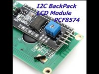
There is no need to develop a "clip on" board to convert i2c to something LCD for the Basic Display Board as these already exist, are readily available and inexpensive. Indeed, many sell LCDs with the 'backpack' already fixed making them i2c based LCDs. I am shortly going to try one of these backpacks on an alphanumeric OLED display that works by HD44780.
I agree that some volume boards will probably need a mute relay. A common location for this is right before the output connector. The main options seem to be either on the output of the volume board or on the output board itself. As it is a relay there is an argument for putting it on a board that's already got a ULN for driving other relays. As an example, your current SE input board has 6 RCA inputs (stereo) and one RCA output with a ULN that has spare channels. Might the mute relay go there just before the output RCA? A philosophical decision with a non-latching mute relay is whether it is normally muted and you need to active the relay to unmute or vice versa.
Much less important but, if a gnd pad were placed between the pads for the crystal on the basic control board, a resonator could be used instead of the crystal. A precision clock is not required for this application. You tag the crystal as 8MHz but higher frequencies would normally be used. Indeed if you only required 8MHz the internal oscillator could be used, eliminating the need for the crystal/resonator.
Geoff
Would it be possible to enhance the control boards so that all the unused MCU pins are taken to a footprint on the pcb so that (2.54mm) headers could be soldered there if desired? This would make those pins available for future experimenters/developers. Vcc and Gnd probably need to be readily available too. I floated this idea in post 42 above where you can see some of the logic for this. For the Basic Control Board there are 7 such pins.
Other reasons might be: a developer might like to have access to the Rx/Tx pins for debugging and your idea of using a simple (linear) pot as a volume control requires access to an analog pin. I have chosen to implement a voltage controlled amplifier (VCA) based on the THAT 2181 and for that I need access to a PWM pin, in particular digital pin 10 (PB2, pin 16). I'm sure others will have their own ideas.
I know I've suggested this before but... I have Bourns rotary encoders - their datasheet (https://www.bourns.com/docs/product-datasheets/pec11h.pdf?sfvrsn=a18340f6_2) recommends a filter circuit including a 10k resistor and 10nF cap. Other manufacturers make similar recommendations. I find this very effective as a hardware debounce circuit in this application (on both the encoder pins and the push button) and eliminates the need for software debouncing. Would it be possible to put footprints on your button board to accommodate these resistors? They could be replaced by wire links if not desired.
There is no need to develop a "clip on" board to convert i2c to something LCD for the Basic Display Board as these already exist, are readily available and inexpensive. Indeed, many sell LCDs with the 'backpack' already fixed making them i2c based LCDs. I am shortly going to try one of these backpacks on an alphanumeric OLED display that works by HD44780.
I agree that some volume boards will probably need a mute relay. A common location for this is right before the output connector. The main options seem to be either on the output of the volume board or on the output board itself. As it is a relay there is an argument for putting it on a board that's already got a ULN for driving other relays. As an example, your current SE input board has 6 RCA inputs (stereo) and one RCA output with a ULN that has spare channels. Might the mute relay go there just before the output RCA? A philosophical decision with a non-latching mute relay is whether it is normally muted and you need to active the relay to unmute or vice versa.
Much less important but, if a gnd pad were placed between the pads for the crystal on the basic control board, a resonator could be used instead of the crystal. A precision clock is not required for this application. You tag the crystal as 8MHz but higher frequencies would normally be used. Indeed if you only required 8MHz the internal oscillator could be used, eliminating the need for the crystal/resonator.
Geoff
Just a couple of suggestions.
Would it be possible to enhance the control boards so that all the unused MCU pins are taken to a footprint on the pcb so that (2.54mm) headers could be soldered there if desired?
Absolutely, but you're getting close to rebuilding an Arduino at some point. Once this is done, you've basically got an Arduino with a more powerful 3.3V and 5V power supply built in. I suppose you could argue that you don't need a Basic Control Board, you could use an external power supply board and an off-the-shelf Arduino to create the same thing.Other reasons might be: a developer might like to have access to the Rx/Tx pins for debugging
A handful of analogue pins are exposed via the buttons header but obviously not all pins are (including PB2). Again, this can be done, but we're building an Arduino 🙂your idea of using a simple (linear) pot as a volume control requires access to an analog pin. I have chosen to implement a voltage controlled amplifier (VCA) based on the THAT 2181 and for that I need access to a PWM pin, in particular digital pin 10 (PB2, pin 16). I'm sure others will have their own ideas.
Ah, but they are included - you just can't see them! The resistors in the suggested filter circuit are pull-up resistors, used when the rotary encoder is connected to 5V. This allows for a wide variety of applications with many devices, many of which are not MCUs. For our implementation, the resistors are included as internal pullup resistors in the MCU. They are there, they're just built into the MCU instead of being discreet components.I know I've suggested this before but... I have Bourns rotary encoders - their datasheet (https://www.bourns.com/docs/product-datasheets/pec11h.pdf?sfvrsn=a18340f6_2) recommends a filter circuit including a 10k resistor and 10nF cap. Other manufacturers make similar recommendations. I find this very effective as a hardware debounce circuit in this application (on both the encoder pins and the push button) and eliminates the need for software debouncing. Would it be possible to put footprints on your button board to accommodate these resistors? They could be replaced by wire links if not desired.
Which is awesome... the only issue is how to connect it. I doubt it has a pin-compatible IDC socket. So perhaps we don't need a piggyback board, but instead we need a "chain breakout board".There is no need to develop a "clip on" board to convert i2c to something LCD for the Basic Display Board as these already exist, are readily available and inexpensive. Indeed, many sell LCDs with the 'backpack' already fixed making them i2c based LCDs. I am shortly going to try one of these backpacks on an alphanumeric OLED display that works by HD44780.
This could get fairly complicated. I suspect there's an easier way though, since the mute relay is only needed to turn off the audio when the power is cut, we can just wire a relay/transistor/resistor circuit to the 5V line. When the power is on, the circuit is unmuted. When the circuit is unpowered, the relay resets and the audio is cut. It can connect to the standard chain connector since that has a 5V feed.I agree that some volume boards will probably need a mute relay. A common location for this is right before the output connector. The main options seem to be either on the output of the volume board or on the output board itself. As it is a relay there is an argument for putting it on a board that's already got a ULN for driving other relays. As an example, your current SE input board has 6 RCA inputs (stereo) and one RCA output with a ULN that has spare channels. Might the mute relay go there just before the output RCA? A philosophical decision with a non-latching mute relay is whether it is normally muted and you need to active the relay to unmute or vice versa.
Can you provide an example component? I'm happy to swap out the footprint. 8MHz/16MHz is entirely at the user's choice. The ATMega328p can even run at 20MHz.Much less important but, if a gnd pad were placed between the pads for the crystal on the basic control board, a resonator could be used instead of the crystal. A precision clock is not required for this application. You tag the crystal as 8MHz but higher frequencies would normally be used. Indeed if you only required 8MHz the internal oscillator could be used, eliminating the need for the crystal/resonator.
Thanks for all the input here!
Phill
Here's the basic board with all pins exposed. Most are already available via the Buttons header, Chain Header and one on the IR header. The remaining pins are now exposed via two additional headers, one for A0 and one for the missing digital pins (DP).


3.3V is available on the IR pin and 5V is available on the Chain header. I can add an extra header for the 5V circuit if needed; this circuit can be switched via pin PD5 (digital pin 5 for Arduino) on the ATMega.
3.3V is available on the IR pin and 5V is available on the Chain header. I can add an extra header for the 5V circuit if needed; this circuit can be switched via pin PD5 (digital pin 5 for Arduino) on the ATMega.
I suppose you could argue that you don't need a Basic Control Board, you could use an external power supply board and an off-the-shelf Arduino to create the same thing.
You make a very valid point 🙂
Ah, but they are included - you just can't see them! The resistors in the suggested filter circuit are pull-up resistors, used when the rotary encoder is connected to 5V. This allows for a wide variety of applications with many devices, many of which are not MCUs. For our implementation, the resistors are included as internal pullup resistors in the MCU. They are there, they're just built into the MCU instead of being discreet components.
I disagree. If you look at the suggested filter circuit again you will see 4 x 10k resistors. The top two are the pull-up resistors that are redundant when the MCU does the pull-up - so omit them from the diagram. What remains are 2 x 10k resistors that sit between the encoder contacts and the capacitors to ground. It's this RC combination that makes the debounce quite effective. And it is these 2 resistors that I am proposing be accommodated with footprints on the buttons board. Actually 3 resistors as this RC combination is also valuable with the push button.
Which is awesome... the only issue is how to connect it. I doubt it has a pin-compatible IDC socket. So perhaps we don't need a piggyback board, but instead we need a "chain breakout board".
All the i2c to LCD 'backpacks' I've seen have four pins (GND, VCC, SDA, SCL) sticking out the end, spaced at 2.54mm - so easy to connect. If you need to chain it, rather than it being at the end of the chain, then a trivial bit of veroboard will suffice. The attached picture is of a backpack fitted to the rear of an lcd.
.... since the mute relay is only needed to turn off the audio when the power is cut ....
Many remote controls come with a 'mute' button which silences the amp whilst, for example you are on the telephone. Pressing 'mute' again unmutes it back at the previous settings. Common with TV remotes too.
Can you provide an example component?
Certainly.
https://www.mouser.co.uk/ProductDet.../CSTLS16M0X53Z-A0?qs=x6vGwhDZZUZCi2wdIsDbVA==
These resonators come with the 2 capacitors built-in, hence the need for the central GND connection.
Geoff
Attachments
You know, I've spent some time looking at this circuit. From what I can tell, the additional resistors add 10K of additional resistance to the A/B terminals over the resistance to the button. The ATMega has ~30K resistors built in (they're the pullups) and the ESP32 has ~47K resistors. I've used the rotary encoders without any external resistors with both MCUs and had no debounce issues, even without any software debounce. I can include them if you're dead-set, but they're simply not required. Try prototyping it yourself without them and you'll see 🙂I disagree. If you look at the suggested filter circuit again you will see 4 x 10k resistors. The top two are the pull-up resistors that are redundant when the MCU does the pull-up - so omit them from the diagram. What remains are 2 x 10k resistors that sit between the encoder contacts and the capacitors to ground. It's this RC combination that makes the debounce quite effective. And it is these 2 resistors that I am proposing be accommodated with footprints on the buttons board. Actually 3 resistors as this RC combination is also valuable with the push button.
Perfect, so a chain breakout board would be ideal here then. Less work and far more useful!All the i2c to LCD 'backpacks' I've seen have four pins (GND, VCC, SDA, SCL) sticking out the end, spaced at 2.54mm - so easy to connect. If you need to chain it, rather than it being at the end of the chain, then a trivial bit of veroboard will suffice. The attached picture is of a backpack fitted to the rear of an lcd.
They sure do. The rotary encoders for this project all have buttons as well, when you press the volume button (instead of rotating) the volume is muted. A mute relay isn't needed to achieve that since we already have two ways of muting the circuit, my favorite being simply setting the volume to zero in software. This is how the code currently works. It's certainly possible to add an i2c-controlled mute circuit although I haven't designed one.Many remote controls come with a 'mute' button which silences the amp whilst, for example you are on the telephone. Pressing 'mute' again unmutes it back at the previous settings. Common with TV remotes too.
We can easily swap out the current crystal and capacitors for a resonator, that helps simplify the board a little!
The Advanced Control Board software is nearing completion, the power button now works (I know, that's an odd thing to say but it's been on my todo list forever) and you can now disable inputs in the UI, so you don't have to cycle through inputs you're not using.
More on that soon!
OK, so a little update.
Software-wise, the Advanced Control Board is working really nicely. I'll try to upload a video in the next few days so you can see the web-UI and how it interacts with the display, etc. Pretty much the only core feature left is the IR control. Other than that, it's pretty much done now, although I'll probably fiddle with it for a while and change a few things.
Now, on the hardware front. Not so good. One piece of advice I must remember: read the data sheet! 🙂
I put the new board with the switching power together (fortunately the power components only) and powered it up. Force of habit is to check the temperature of the LDOs as soon as I power up the board - I'm glad I did, the 5V regulator was so hot I nearly burned my finger. I checked my caps, soldering, quick glance of the datasheet and all looked good. Powered it back up and... red hot. I stuck a meter across quickly and it was reading nearly 7.5V. Not good. I did some research, nothing obvious. A more detailed read of the datasheet revealed my mistake: the LDO's MAX input voltage is 6V. Now why an LDO exists that's 6V in, 5V out is beyond me, but the fact that my rectified voltage is close to 9V explains why the LDO was less than happy! Read the datasheet!
Fortunately I found a drop-in replacement but it doesn't require one of the resistors on the board, so I've rev'ed the boards to drop the resistor and reduce the footprint of the boards. They're pretty tiny now!
New components are here, I'll repopulate the existing boards for the power circuit and I've got new boards ordered, so I'm just waiting for them now. My chassis is in production (looking forward to getting that, thanks DIYaudio Shop 🙂 ) and then I can actually put the whole thing together!
It's been quiet for a while, I was waiting for my case and a few components to arrive, then I was away for a while. Good news though, the case has turned up and I've been working on my final build with the final boards, now they're stuffed. You may have noticed new photos of the boards appearing on the first post, but here's an update on my actual project!
The case is here and I have to say the guys here at diyaudio did a fantastic job. My design was fairly complex so I ended up working with the engineer in Italy, who took the time to understand what I was trying to do and was very patient! The final product looks great, I think. Simple and classic.

It was really hard to find the knobs I wanted for the rotary encoders, these came from AliExpress in the end. The screen is the one from Newhaven in the first post and the power button is from eBay, a simple momentary button with a built-in LED.
The build isn't finished yet (as you can probably tell from the blue tape) but it's getting close. The RCA sockets on the input and output boards aren't right - they won't work with any panels thicker than 1mm in reality, so I removed mine and I'm adding panel mounted ones. I'll update the PCB to remove the RCA sockets and include a three-pin header instead which will offer far more flexibility for cases. Other than the RCAs, everything is wired up. The IDC connectors that connect the boards are hard to see because they're the same color as the case, but it's all wired up.


And here it is powered on!

The forum doesn't seem to support videos, but here's a short video of operation. I'll upload one showing the web UI soon.
https://i.imgur.com/GwbWEbn.mp4
Phill
The case is here and I have to say the guys here at diyaudio did a fantastic job. My design was fairly complex so I ended up working with the engineer in Italy, who took the time to understand what I was trying to do and was very patient! The final product looks great, I think. Simple and classic.
It was really hard to find the knobs I wanted for the rotary encoders, these came from AliExpress in the end. The screen is the one from Newhaven in the first post and the power button is from eBay, a simple momentary button with a built-in LED.
The build isn't finished yet (as you can probably tell from the blue tape) but it's getting close. The RCA sockets on the input and output boards aren't right - they won't work with any panels thicker than 1mm in reality, so I removed mine and I'm adding panel mounted ones. I'll update the PCB to remove the RCA sockets and include a three-pin header instead which will offer far more flexibility for cases. Other than the RCAs, everything is wired up. The IDC connectors that connect the boards are hard to see because they're the same color as the case, but it's all wired up.
And here it is powered on!
The forum doesn't seem to support videos, but here's a short video of operation. I'll upload one showing the web UI soon.
https://i.imgur.com/GwbWEbn.mp4
Phill
Great build, could you post the link for the antenna and the extension wire to the rear panel you had choose (i didn't find it in the BOM)
Really nice work Phil! Case and internals look tidy and elegant.
I can sympathise here. I've ordered so many knobs from Ebay and Aliexpress trying to find the right one!
It was really hard to find the knobs I wanted for the rotary encoders, these came from AliExpress in the end
I can sympathise here. I've ordered so many knobs from Ebay and Aliexpress trying to find the right one!
At least I'm not the only one! Then you have to get them to fit the case... I wanted them countersunk into the face plate since my encoders have push buttons as well. Finding ones that were centered and consistently sized... not easy! There's a lot of junk on AliExpress/eBay.I can sympathise here. I've ordered so many knobs from Ebay and Aliexpress trying to find the right one!
This was actually one of a two-pack from another project. I can't remember where they came from - may even have been Amazon, but if you're looking for one then this is what I would order now:Great build, could you post the link for the antenna and the extension wire to the rear panel you had choose (i didn't find it in the BOM)
Blocked
Just make sure the length is going to work for you.
Well, it's finally up and running in my setup! Works like a charm and seems to have opened up the soundstage a little, from a small amount of listening (hard to get anything serious in with a three-year-old running around like a maniac).
The only issue I have is volume levels; it's paired with two Rotel RB980BX power amplifiers in bridged mono - they provide plenty of oomph, but they open up real fast. My speakers are a pair of KEF R11s that I love, but they're pretty sensitive at 90dB @ 2.83v/1m. The result is that even at the lowest volume setting, they're pretty loud. It's no disaster for me because my room is pretty big and I wouldn't listen any quieter anyway, but if you're thinking about building this for yourself and you have a similar setup (powerful amps and sensitive speakers) then you might want to consider upping the resistors in the relay attenuator. However, bear in mind that the impedance of the preamp increases so make sure your power amps can deal with the impedance, or put in a buffer of some sort to control it.
I can honestly say I've learned a lot from this project. Some of that is leading to one final revision of the input and output boards:
I'll upload the last set of input boards later today for anyone who needs them. The software is pretty much finished too, it's all at the GitHub link for the Advanced Control Board. The Basic Control Board is there for those who would rather work with the ATMega328p, but honestly, I'd probably use the ESP32-based Advanced Control Board. It sill leverages the Arduino framework, so it's just as easy to develop, it's way faster and it's pretty much the same price. Do as you wish, but that's my advice for this project!
Phill
The only issue I have is volume levels; it's paired with two Rotel RB980BX power amplifiers in bridged mono - they provide plenty of oomph, but they open up real fast. My speakers are a pair of KEF R11s that I love, but they're pretty sensitive at 90dB @ 2.83v/1m. The result is that even at the lowest volume setting, they're pretty loud. It's no disaster for me because my room is pretty big and I wouldn't listen any quieter anyway, but if you're thinking about building this for yourself and you have a similar setup (powerful amps and sensitive speakers) then you might want to consider upping the resistors in the relay attenuator. However, bear in mind that the impedance of the preamp increases so make sure your power amps can deal with the impedance, or put in a buffer of some sort to control it.
I can honestly say I've learned a lot from this project. Some of that is leading to one final revision of the input and output boards:
- Make sure your panel mounts will mount your panels. Sounds obvious, but 3mm rear panels (like I have on the Slimline chassis with Aluminium panels for CNC work) are really thick. Virtually all PCB-mounted RCA sockets will NOT fit. You will need panel-mounted ones.
- The Espressif ESP32 is really hard to blow up
- If you think that building your own is cheaper than buying something, you're probably wrong. If you're going to follow my designs, it probably will be (because I've done the very expensive work of iterating the boards!) but creating your own from scratch is going to be expensive. But trust me, building your own is much more fun!
- Chassis design is hard. I've had to order a replacement rear panel and my unit doesn't fit inside my current hifi stand because it's too deep!
- The Espressif ESP32 really is very hard to blow up
- Read all the specs for any components you're looking at using. Read measurements, panel thicknesses, tolerances. Don't skip anything or make any assumptions
- It's going to take longer than you think. But don't let that put you off.
- Last of all, it's the most satisfying project I've ever completed (and that list includes restoring a 1960 Wurlitzer 2400S jukebox!). It's well worth the time and effort to be able to stand back and say "I did that"!
I'll upload the last set of input boards later today for anyone who needs them. The software is pretty much finished too, it's all at the GitHub link for the Advanced Control Board. The Basic Control Board is there for those who would rather work with the ATMega328p, but honestly, I'd probably use the ESP32-based Advanced Control Board. It sill leverages the Arduino framework, so it's just as easy to develop, it's way faster and it's pretty much the same price. Do as you wish, but that's my advice for this project!
Phill
Hi Phil,
great work which inspired me to design something similiar. Did you publish the schematics and Board layout on easyEDA?
great work which inspired me to design something similiar. Did you publish the schematics and Board layout on easyEDA?
I put most of it on GitHub - the schematics, PCB and BOM are there for the Advanced Control Board, Volume Control board and the Convenience and Mute boards. I've just realized that the balanced input and output boards are missing, as is the SE to Balanced daughterboard, so I'll get those uploaded later today (when the kids aren't around "helping" me).
OK, I updated the GitHub repository so everything should be on there now. If you have any questions, just ask and I'll do my best to answer
https://github.com/gilphilbert/falk/tree/main/pa-01
https://github.com/gilphilbert/falk/tree/main/pa-01

- Home
- Source & Line
- Analog Line Level
- Modular Preamp Design