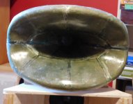
These pics are the WN_SEL_425_A4 made in fiberglass composite. The bare fiberglass horn is 1.5Kg and the CLD (rubber and plaster) increase that to 5.9Kg (wet) that should reduce to total 4.5Kg (cured). It's about the same mass as my DE75TN driver.
Hopefully these pics stay in the right order. [EDIT] the pic order is scrambled again , new pic# in brackets), anyone know how to fix this ?
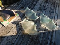
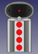
pic#1 (1) - horn plug mold (1/2 symmetry, R22mm RO added, 57cmx38cm) with skins curing in the sun
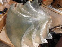
pic#2 (8 )- the 4 skins that I need for 2 horns
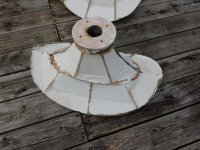
pic#3 (7 )- gluing the horn halfs together
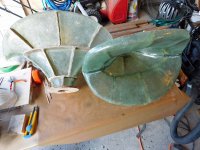
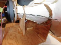
pic#4 (6) - flash trimmed and wood stiffeners added (it's now about stiffness of an ABS horn)
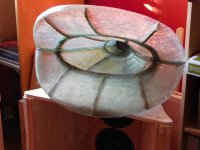
pic#5 (5 )- trying a translucent horn, but I would like more damping and stiffness
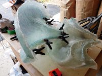
pic#6 (4) - CLD composite, layer silicone rubber 2-3mm thick + sand dusting for the next layer
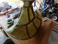
pic#7 (3) - CLD composite, layer plaster of paris 1-2cm thick, poured into pockets
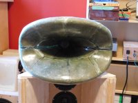
pic#8 (2) - CLD complete, ready for intial tests, before any finishing (filler+sanding+paint)
Hopefully these pics stay in the right order. [EDIT] the pic order is scrambled again , new pic# in brackets), anyone know how to fix this ?
pic#1 (1) - horn plug mold (1/2 symmetry, R22mm RO added, 57cmx38cm) with skins curing in the sun
pic#2 (8 )- the 4 skins that I need for 2 horns
pic#3 (7 )- gluing the horn halfs together
pic#4 (6) - flash trimmed and wood stiffeners added (it's now about stiffness of an ABS horn)
pic#5 (5 )- trying a translucent horn, but I would like more damping and stiffness
pic#6 (4) - CLD composite, layer silicone rubber 2-3mm thick + sand dusting for the next layer
pic#7 (3) - CLD composite, layer plaster of paris 1-2cm thick, poured into pockets
pic#8 (2) - CLD complete, ready for intial tests, before any finishing (filler+sanding+paint)
Attachments
Last edited:

Initial measurements WN_SEL_425_A4. These were taken indoors (gated 6ms) using a D2200Ph driver). These will be repeated for my preferred DE75TN.
The horn has a very good power response, imaging is excellent and it "disappears" better than the ZXPC horns. I still need to repeat the tests with my preferred DE75TN (they're still bolted to ZXPC horns).
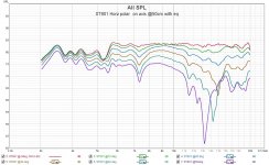
pic#1 - horizontal polars (no EQ, no BP) using D2200Ph to see if its working properly (and it is).
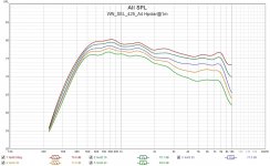
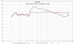
pic#2 - on axis EQ and BP filter (500-7Khz) applied
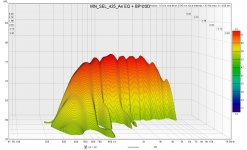
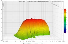
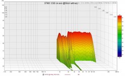
pic#3 - CSD waterfall to check for misbehaviour (nothing serious). There is some low level stuff around 1Khz, 2Khz that may be reduced when I make a proper craddle mount. Overall I'm happy with the results.
The horn has a very good power response, imaging is excellent and it "disappears" better than the ZXPC horns. I still need to repeat the tests with my preferred DE75TN (they're still bolted to ZXPC horns).
pic#1 - horizontal polars (no EQ, no BP) using D2200Ph to see if its working properly (and it is).
pic#2 - on axis EQ and BP filter (500-7Khz) applied
pic#3 - CSD waterfall to check for misbehaviour (nothing serious). There is some low level stuff around 1Khz, 2Khz that may be reduced when I make a proper craddle mount. Overall I'm happy with the results.
Attachments
Very cool! Will there some sort of wrap around the plaster layer? I wonder if this approach would also work for my printed horn.
Thanks. I was initially going to trowel a bit more plaster paste, to smooth the surface, then use latex paint to seal it. The plaster was a brute force "fill" to add mass and stiffness (and it works 🙂 ).
I think you could do something similar to a PLA printed horn. I'm currently looking for another fill material that has mass/stiffness and is spreadable/pourable on curved surfaces and will not chip like plaster.
I think you could do something similar to a PLA printed horn. I'm currently looking for another fill material that has mass/stiffness and is spreadable/pourable on curved surfaces and will not chip like plaster.
What is the challenge for mating a cone to a horn?? It would seem no less or more challenging than the compression driver, this is why I ask.I still have interest in horns on cones/domes, I built a few midrange horns with small drivers and was never able to get the range I wanted (500Hz-5KHz) without excessive EQ. It was easier with a 2inch CD. It would be interesting to compare the two solutions. I think it would require a phase plug for the cone as well as the 2inch adapter if the ZXPC horns were used. Maybe easier to start from scratch.
The cone/horn HF is more challenging because there is typically more mass (FR rolls off sooner), and you probably need to design a phase plug (depends on upper freq) and the mount is custom. In contrast, the CD usually has a good motor, low mass diaphragm, the phase plug is built in, and the mounts are standard.
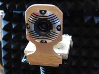
The WN_SEL_425_A4 with a horn stand and the DE75TN driver.
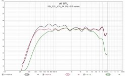
Pic#3 shows the FR effects of various lower cutoff freqs [300,350,400,500Hz]. It's possible to cross lower than 500Hz with this driver and horn.
Pic#3 shows the FR effects of various lower cutoff freqs [300,350,400,500Hz]. It's possible to cross lower than 500Hz with this driver and horn.
Attachments

Custom Horn WN_SEL_270_A5_M5 - Spherical Horns
The previous tests using a DE75TN shows it's possible to cross the driver lower than 500Hz. However, it would be easier if there was more LF loading and better if the mouth was larger mouth to the control the pattern to a lower freq. I like the WN_SEL_425_A4, and this next horn will be used to push the XO a bit lower to see if I like it as well.
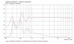
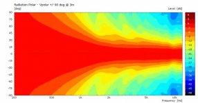
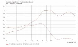
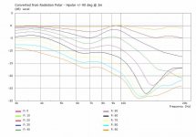
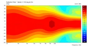
The WN_SEL_270_A5_M5 is my second horn designed by @docali (many thanks again) (@ https://sphericalhorns.net/ ) using his calculator. The WN_SEL_275_A5_M5 is also a super ellipse, ~70x50deg coverage, with loading to 300Hz for a 2inch driver. Pics for the model, polars and radiation impedance are below.
Attachments
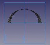
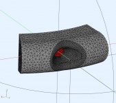
The plug mold is made from XPS slices covered in fiberglass cloth and marine epoxy to protect it from the polyester resin. That's the summary, these are the details.
The 1/2 symmetry mesh model was reduced by 3mm (FreeCad, normal to all elements) and cross sectioned into slices the width of the XPS used. The 3mm reduction accounts for a single layer of 6oz fiberglass cloth, the epoxy and filler (microspheres). XPS is really easy to work with using a hot wire to cut it (melt it) and XPS comes in standard widths (0.25in, 0.5in, 1in, 2in). The reduced slice (pic#1, example) can be printed on paper and has the front and rear profiles of that slice. The FreeCad origin grid is also printed and used for registration marks. The FreeCad display scaling is corrected using a macro, and checked after printing (it has a known 2inch throat). The slices are fine (0.5in or better) near the throat (first 6-8in) then can be more coarse for the rest (1-2in). The slices are aligned and glued then merged using boxcutter/sanding/filler and checked using printed slice template (foamboard is good for templates). Overall there can be some dimension variation, from the ideal, between the slice boundaries (edge-edge) but overall the average area expansion will be correct. The roundover was added using foam pipe insulation for the fiberglass mold and was placed tangential to the horn mouth. Then the entire structure is dimensional checked using templates and contour gauge (measures actual) then corrected with filler and sanded. Then several layers of furniture wax (Johnson SC) was applied to prevent the PVA release compound from bonding to the plug. It sounds more complex that it actually is 🙂 and definitely needs to be done in a well ventilated area. The casts are made with fiberglass matt (1.6oz) and polyester resin (non waxed formula).
I think it might be easier to 3D print the mold, However, that's easy for me to say as I don't have a 3D printer yet (but it's on my wish list) 🙂.
Attachments
Thanks! 3D printing would be much easier for sure. Or maybe cutting the mold in pieces on my CNC. I admire the amount of hand work in your process. I think I need to try laminating one day...when I feel brave enough to do so🙂
Thanks, It's a time tradeoff between more work for a mold plug (days), but then less time (30min) per mold cast.
V16 WN270 midrange horn
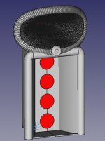
I was thinking about how to incorporate a tweeter, before starting the next midrange horn build, The WN270 is larger and I wanted the tweeter to be more integrated with the midrange horn.
The attached pics (aka Werlitzer jukebox) shows the next update (WN270 midrange horn) with R40mm roundovers and the tweeter incorporated into the midrange's round over. There are a few options for the tweeter, the one shown is a Dayton ST601 bullet tweeter. I need about 60deg coverage ( ~1.1sr), so the shallow model was selected. I still need to do some preliminary measurements to see how they perform, and the results will be posted.
Attachments
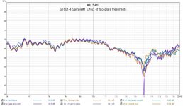
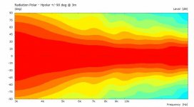
Dayton ST601-4 Bullet Tweeter Measurements
I bought a pair of these tweeters Dayton ST601-4. They are well constructed, the faceplate appears to be cast aluminum. I do wonder why they put contour ridges in the faceplate, I would wave preferred smooth. They are sold in pairs and these measurements are for a single sample,
A few interesting observations. The -6dB off axis is avg 70deg so its wide enough for the power response I want. There is an off axis dip @7.4Khz that could be the faceplate or possibly my test mount, that needs some investigation. The CSD looks very clean in the range I would be using (7Khz-20Khz). There are minor resonances at 5.6KHz and 19.8Khz but the rest is very clean.
pic#1 : driver mounted in a test fixture
pic#2 : driver FR on axis@50cm, series cap bypassed, both raw and EQ'd response
pic#3 : horizontal polar 0-50deg, @50cm
pic#4 : CSD waterfall
Attachments
That's correct, the DE75TN fades at 8-9Khz like most of the 2" CDs. The alternative would be a coax CD but they're still expensive. This is an easy way to get the last octave clean (for me that's 7-14Khz 🙂)
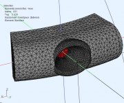
I was interested in the cause of various polar dips of the ST601. I also built a model to try more drastic changes, but abandoned the idea. At these freq the wavefront is very directional and the polar shape is inherent in the design. I'll still give this a listen when the WN270 is built, just to get a listening impression. I think a tiny horn would perform better.
Pic#1 : the actual ST601 all measurements @30deg off axis, with various roundovers and faceplate smoothing - no real change
Pic#2 : AKABAK model of the ST601, using ring radiator, with measured dimensions
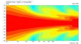
Pic#3-6 : AKABAK model normalized polar plot, curves, RadImp
Pic#1 : the actual ST601 all measurements @30deg off axis, with various roundovers and faceplate smoothing - no real change
Pic#2 : AKABAK model of the ST601, using ring radiator, with measured dimensions
Pic#3-6 : AKABAK model normalized polar plot, curves, RadImp
Attachments

Tiny horns.
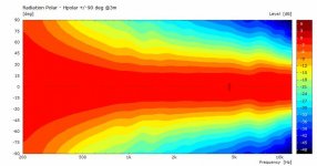
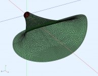
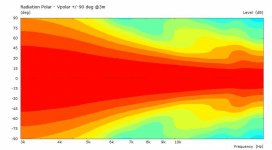
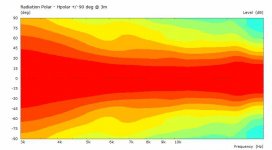
This is a AKABAK model of a small tweeter horn fitted into a section of the curved R40mm RO that will be used in the WN270. The same tweeter horn is used on all 3 models, just the mouth termination to the RO is different. This was to see how sensitive the results are to the final mouth shape.
The horn is OSWG-ish (rough dimensions calculated using Hornresp rectangular uniform aspect ratio) but it's actually formed using a quadratic throat, ellipse conic, then blended into the RO. The horn is W:110mm x H:75mm x D:65mm and would use a 1 inch CD.
Attachments
-
 model8f-Hpolar.jpg20.2 KB · Views: 122
 -
 model 8f.jpg69.4 KB · Views: 128
 -
 model8e -Vpolar.jpg21.8 KB · Views: 117
 -
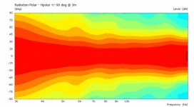 model8e -Hpolar.jpg20.3 KB · Views: 114
 -
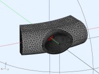 model8e.jpg55.8 KB · Views: 129
 -
 model8d-Vpolar.jpg20.1 KB · Views: 108
 -
 model8d-Hpolar.jpg19.4 KB · Views: 117
 -
 model8d.jpg96.4 KB · Views: 119
 -
 model8f-Vpolar.jpg20.6 KB · Views: 118
Very interesting results and nice and elegant integration of the hf part.
Have you ever thought about to try a k-tube with a similar integration? Maybe a very short one slightly angled down.
Have you ever thought about to try a k-tube with a similar integration? Maybe a very short one slightly angled down.
Thanks, I forgot about the K-tube. I went back to look at the simulations I did for them K-tube . It would be easy to add one, since the tube has a small cross section. That is also a disadvantage because the mouth is small and I would like better control of the wavefront DI ( similar to the WN270).
I'm also looking into AMT/Planar or dome tweeters with a tiny horn. These horns would be small enough to 3D print or fiberglass in a single piece.
I'm also looking into AMT/Planar or dome tweeters with a tiny horn. These horns would be small enough to 3D print or fiberglass in a single piece.
- Home
- Loudspeakers
- Multi-Way
- Modular active 3 way - work in progress