The WM8804 uses a PLL to recover the clock from the SPDIF and then reclocks it. Recovery bandwidth is down to 100hz, so it would be good to insure a clean signal with no phase shift down to say 10x lower in frequency or 10hz. The input impedance of the WM8804 spdif pin is 23kohm. A 10hz cutoff with a 23kohm impedance gives a capacitor size of 0.69uf. Using the BOM 0.1uf capacitor gives a cutoff frequency of 69hz. So by my simple calculation, a capacitor of 0.68uf or bigger is probably good enough. I wasn't this scientific when I made the change. I just grabbed a capacitor and soldered it in and listened. It was only after the fact that I thought about why it should make a difference. I used a 3.3uf Wima MKS in parallel with the original 0.1uf MLCC. I didn't try other combinations so I can't give advice other than on the recommended size for the capacitor. But if my theory is right then one should see similar benefit with capacitors of 0.68uf or bigger.Yes read it with great interest; As i have in my tool box 0,2 uF MKC or 3,3 uF wima MKS (=MKT) I choose MKC because you talk about it for its special properties. Do you think the no MKC WIma will be better ? Where was the difference ? Band pass in the low frequency (I think it was the reason of the "wrong direction" ?)
---Gary
Anyone tried the V3 DAC with the Salas PSU with buffer?
Am I the first one to try this set up ?
You wait a bit n let you know later.
Any news about Salas reg?
i have been testing expensive 390 uF Nichicon FP cap at C18... worse than the 100 uF of the BOM. With this last and less expensive one it is here less glitchy ant "timbres" are better.
Just IMHO in my system and it was with 470 uF SEPC at C22 in both test.
Just IMHO in my system and it was with 470 uF SEPC at C22 in both test.
Any news about Salas reg?
Still waiting for some parts to come.
Will certainly post after finished.
JP - I am sorry to contradict you but this is wrong. The spdif input capacitor is always needed. As I mentioned earlier, the spdif input pin of the WM8804 (pin 20) needs to float at 1/2 Vdd = ~ 1.65v. To prove this out to myself I did a simple experiment. With power off, I used a clip lead to bypass C4 with a 30ohm resistor. I then turned on the DAC and as expected there was no sound. As soon as I unclipped the resistor the DAC began to play music. So I am confident in my comments.
---Gary
You are absolutely right, the cap can be omitted at the source not in the DAC (if there are caps in series). Drawback would be that the source can not be used just like that with other DACs. Excuse me for the confusion, got this in my head when I was optimizing matters (got used to do that but maybe better try first before speaking out thoughts) but my sources are even direct coupled so I will try transformers.
Last edited:
i have been testing expensive 390 uF Nichicon FP cap at C18... worse than the 100 uF of the BOM. With this last and less expensive one it is here less glitchy ant "timbres" are better.
Just IMHO in my system and it was with 470 uF SEPC at C22 in both test.
Have been testing from this morning C18: The best test was with a Black Gate BG-N 33 uf/16V.
This is the second time I notice that a mix with the SEPC is a good match for "digital" signal powersupply...
The to bright side in the highs disappear with no lake of resolution... But the better add on is the tonal balance with difficult instruments like piano, bass, harmonica : better timbre and tonal balance. Fleshier...
i know this is 3 x less than the 100 uF and 12 x less than the 390 uF of the last test... but still with the 470 SEPC at C22. The smd caps 4.7 uF stay.
The power supply is the one of the BOM with 2 x 2200 uF but without the 0,1uF before the first cap.
You never know !
Jean-pierre, did you test SAL-PM cap at C18 or not... can test myself because have none !
regards
Eldam
Last edited:
Still waiting for some parts to come.
Will certainly post after finished.
Are you thinking to bypass the on board regs by Salas regs or you are thinking to use the Salas as main 5V PSU of dac (before the on board regs)?
Last edited:
Putting a low value PPS capacitor in parallel with the C31 ceramic one?
I was wondering if adding a PPS capacitor at 0.047uF in parallel with the C31ceramic one could make a noticeable and maybe positive difference?
The reason for the 0.047uF value is that it is available in the 1206 size that would make it possible to add in parallel with the ceramic I got there, without piggy backing the capacitors.
With regards
Martin
Any added stray capacitance or inductance may not have the result one would think of the cocktail. If I understand the meaning of your post right you mean to parallel caps on 1 footprint ? Don't do that.
IMO : C34 a 1 µF ceramic X7R cap, C32 a WIMA 1 µF MKS-2 and C31 also a 1 µF ceramic.
GaryB uses 4.7 µF for the Wima. You could try out 2.2 µF MKS2 for a change. Just try not to go over 10 µF in total.
Or make C34 a 4.7 µF ceramic cap//1 µF MKS2//1 µF X7R....<- interesting combo !
I stopped using PPS that often as I did before as they break easily. Too easy IMO. Sound good but are weak mechanically. Maybe they exist in a molded version ?
BTW I almost forgot: I found excellent 1 µF caps for C32 in my own stock. Sound very good and they're miniature. Older encapsulated (so airtight) OSCON series made for a japanese contractor.
Last edited:
Ok I will skip the paralleled caps on one footprint. But I do have the PPS 0.1uF in a 1210 size, and will try it for C31 when I increase the C34 to 4.7uF as you suggested. I will get the c35 in a 2.2uF, and 3.3uF to try as well.
I am using the 1uF mks2 for C32 as of now.
I do think Evox Rifa make molded ones of the PPS capacitors, I think Distrelec got them in stock.
Thanks Jean-Paul
With regards
Martin
I am using the 1uF mks2 for C32 as of now.
I do think Evox Rifa make molded ones of the PPS capacitors, I think Distrelec got them in stock.
Thanks Jean-Paul
With regards
Martin
Last edited:
About the JG Buffer EUVL revision than some will use with the Subbu:
I notice it's designed for 4.7 n caps shunt at the outputs of the ES sabre Dac chips instead the "big" 10 nano MKT of the Subbu official BOM.
As I'm not technician I don't know if it's important to notice it or not...
And Daniel (Curryman) prefer PPS smd caps to the others like Wima FKP with the EUVL/JG buffer for the sound result.... think about it for you BOM at Mouser....
My understanding is that the 470R and shunt capacitor 150 P are not used at the entry of the Buffer because of the matched FET.
Ask confirmation to Mark or Patrick.
I wil ask if a PPS smd caps will improve C4 (spidf input) on the Subbu Dac instead MKT caps ? But I think Jean-Paul try it or avoid it because it's fragile with the heat of the iron ????
If somebody want to test it if the BOM is not sent by Korben, think to try the 0.68 uF value as GarryB notice a better result with it.
regards
Hope it helps, I post here because it's the modification thread of the Subbu.
Last edited:
Sorry Eldam, I think you just mix up too many things and you are now also adding erroneous things. We never used 10 nF at the output !?!? Just one item at the time would make things less chaotique....
You seem to notice it and you have ears that work so...
Regarding the last item of the input cap (C4), you can up it to 1 µF if you like. Use the dielectric that's in fashion in la douce France at the moment if you like but please be aware that this is the entree digitale.... I suggest the simple but good Wima MKS2 film cap.
And...changes just because they're changes...is that what you seek ? I strongly suggest to ask one question at the time and to give each question a number. Please...
As I'm not technician I don't know if it's important to notice it or not...
You seem to notice it and you have ears that work so...
Regarding the last item of the input cap (C4), you can up it to 1 µF if you like. Use the dielectric that's in fashion in la douce France at the moment if you like but please be aware that this is the entree digitale.... I suggest the simple but good Wima MKS2 film cap.
And...changes just because they're changes...is that what you seek ? I strongly suggest to ask one question at the time and to give each question a number. Please...
Last edited:
thanks,
sorry you right, make too much things and make mistakes.
Sorry for others the Subbu have 4.7 Nano at the output and no 10 nano as I wrote...
Wes good method, step by step...
Thanks for the tips... no speacial fashion in France but the minini skirts.... some try with tressed kevlar... it's lighter.... here is the eternal Douce France (for cliché add the technologicals devices you like here : camenbert cheese, glass of wine, baguettes, femmes fatales) !
With my few knowledge I will put a huge polysteren cap like a RTX MIT.... but as I said I'm no technician, but I like to learn. I try the GaryB tip with 3 MKC to grow to 0,660 nano but have to say it's a little stupid to have multiple points of solderings and caps for "digital" signal... come back with the 0.220 uF MKC. If Wima MKS is good enough in quality, I got one of 1 uF instead of a modern fashion 1 uF smd PPS cap !
Last edited:
Create a basic design, build it, test it, improve it. When ready re-evaluate, improve and challenge yourself to make it better. When you think you are ready ask yourself the same questions again.
Kaizen/改善:
Kaizen - Wikipedia, the free encyclopedia
Good thing is that most of this has already been done for you. It really is better to keep to the BOM and do 1 change at a time.
Kaizen/改善:
Kaizen - Wikipedia, the free encyclopedia
Good thing is that most of this has already been done for you. It really is better to keep to the BOM and do 1 change at a time.
femmes fatales !
Last time I saw one was long ago. Since the crisis started most of them turned out less fatale and went for stability probably for economic reasons 😉
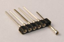
DON'T use large caps in this DAC. It needs small parts with shortest possible wiring. If you want to experiment you can use the pins of the better IC sockets to test various caps. Or these which are more or less the same. The V3 PCB won't survive too many solderings so using a socket seems wise.
Attachments
Last edited:
Yes I'm sure of it and have no doubt about that and sure you turn the Wheel 30 times... but as you said we are all on the same Wheel at Earth.... and french like fashions... that's why we got Lanvin, Diorr, .... the Wheel and the models are turned 3000 times (bad joke, but we want not to save the clichés here !)
Point being that fashion does not change what is in the clothing. No clichés but this design is to deliver not to be fashion.
Point being that fashion does not change what is in the clothing.
Sure...here please keep the long legs....
For the eyes... you maybe wrong but for the ears you absolutly right. But sometimes we more carefully listened the fashioned women... have to think twice about that annd have a mindfulness meditation with that question 😕 ... but wife said I have to clean the washing machine first !
JP, I'm sure now your wisdom is big enough to look at this "excelent" comic french movie : "les tontons flingueurs"
Sory to be off topic, let's come back to the Subbu....
Last edited:
- Home
- Vendor's Bazaar
- Modifying the Subbu V3 DAC