
Which capacities and voltages did you get? I'm thinking of getting the largest ones 63V. On Mouser it says that some of them are at the end of their life and some of them are new, so they could be different despite the same PEG227 family. Probably same manufacturing process though.
PEG227MMS4280QE4
https://eu.mouser.com/ProductDetail/KEMET/PEG227MMS4280QE4?qs=T%2BzbugeAwjhWYlu91lRSbA==
PEG227MMS4280QE4
https://eu.mouser.com/ProductDetail/KEMET/PEG227MMS4280QE4?qs=T%2BzbugeAwjhWYlu91lRSbA==
Last edited:
I got
2.8 mF / 63 V, measured 2,65 mF both
5,2 mF / 40 V, measured 5,45 both
10,5 mF / 25 V, measured 10,8 both
All within tolerance.
I would buy. End of their life: in 50 years;-?
You once linked to PEG130. I think these will also sound great.
Just buy, they are far above average. They are worth the money.
![DSCN0603[1].JPG](/community/data/attachments/1262/1262988-ae15a6b7999d7ef098411acd518a9e8f.jpg?hash=rhWmt5mdfv)
Hello, friends.
I'm sleep deprived and super busy, but got my BD441s and replaced the output and bias (I had BD139) transistors. These do have extreme clarity and detail to the point that the music seems to have an entire layer of ambience that was lost somewhere in the noise previously.
One of the 12 BD441s I ordered measures very differently and looks different. Not just a different batch, but a different era it would seem. Haven't listened to it yet, but Ube is quite a bit higher than my BD442s. Higher current and amplification too.
I'm sleepy. Waking up early too. I'll enjoy the music for now. Thanks for sticking around and keeping this project/idea alive. I shall finish mine sooner or later I believe. Also received HE6se v2 from Hifiman today. This will be very useful to discern subtle differences between components once I make my cables and resurrect both channels into working order.
Oh and I measured the big KEMETs. Only one of them saw action and it measures lower than the unused one - 19.6mF vs 20.3mF.
Ordered PEG227 today.
Love you all
Respectfully
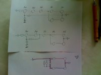
I used the same colors as the PA-940 circuit:
This illustration of the NAD circuit is confusing, irritating. I have made a dozen misreadings;-)
- the green soft clipping area at the bottom left. Disadvantageous in terms of sound. Must be separated by C409! The switch on the back of the device is not enough.
- top left the orange-pink area: corresponds to the PA-940 R3. R3 is all you need! All this hocus pocus unnecessarily modulates the current, disadvantageous.
- what two transistors do as a volt amp in the PA-940, three transistors do in the NAD. Two would have sufficed here too - two phase inversions (Q401 + Q405) result in the correct phase again. In the NAD, a "buffer" is connected (Q407), unnecessarily, disadvantageous.
- the middle green area is the bias control, including C429, which best bridges the entire control with the entire frequency range.
- the yellow area is the feedback. Here with the NAD an unnecessarily complex network, which can be heard: several circuits that smear the signal, disadvantageous. R429 is sufficient.
- the blue area in the middle is the bootstrap capacitor. It only makes noise and dirt.
- the blue thing on the right is a "breaker", a "fuse", E401. Sounds bad and is unnecessary.
- on the right is the 2 stage complementary transistor push-pull follower, marked red, pos. half wave, and blue - neg. half wave.
This illustration of the NAD circuit is confusing, irritating. I have made a dozen misreadings;-)
Attachments

Last edited:
I have drawn the principle circuit diagram of the NAD again. Above with the original over all feedback.
Since I want to keep the NAD circuit final (It is a friend's NAD - I also have his loudspeakers and will rework them and adapt them to the NAD) - 3 stages preamplifier, two stages PP power follower, but want to keep the special sound of the Folger, I will later limit the feedback to the two voltage amplifiers. Because these make the noise without feedback.
The bottom picture shows the push-pull stage again. Here with the bias network and a capacitor recommendation. Many do without this capacitor, others only use a small capacitor.
What many people are not fully aware of is that the AC signal must pass through this bias regulator as unchanged as possible so that the - in this case negative - other half-wave can be amplified. In any case, the regulator is a double PN junction and also the resistor network. No one can say what will come out on the other side, when and how: it is "non-linear".
I recommend bridging the entire regulator by means of a capacitance that is oriented to the sum of the resistors involved, cut-off frequency < 20 Hz. Then also take into account in AC withstand of this capacitor. The expected signal voltage is much higher than the set "bias voltage".
Use the cleanest and clearest and most neutral one.
But also the bias transistor is elementary for the sound: here, too, use the best-sounding, cleanest and clearest, most neutral one, because its current quality is clearly audible, see e.g. observation #102, #125.
Attachments
Aside, and again)-:
I listen to this single-stage complementary transistor push-pull follower - with now again appropriately low C-B resistance; I would also consider these resistances for audio tuning - and switch to an SE, same transistor, quasi same power supply, 12 V, 1 A only, and again the listening experience: a complementary push-pull sounds broken, gray, dirty, flat, slowed down, no flow... that has, in comparison, nothing to do with audio. Reasons are not e.g. different internal resistances or anything else.
The ear is a difference detector. Tones are complexes of frequencies that have a beginning and an end, that have a boundary and difference to other complexes of frequency. A push-pull amplifier with different sounding half-waves obviously makes a number of mistakes in this respect that are recognizable to the ear (Aside, I recently heard four BD711s, two different batches. Both batches not suitable for audio, but one slightly finer, milder, cleaner, grander. Same type, different batches.). An orientation to e.g. only frequency has nothing to do with audio. And I'm talking about just one complementary transistors push-pull stage. An additional, second stage, e.g. as a driver, reinforces this negative impression.
Some of the finest SE amplifiers can be found here: https://www.diyaudio.com/community/forums/pass-labs.8/ 😉
Rebuilt the SE today for the PNP transistor test marathon. From BD441 to BD442: they definitely sound different: I had to move the speakers 4 - 5 cm apart to get a balanced stage again. The 442 sounds (sounded, even earlier) "blacker", clearer, has a much finer grain. It is smaller, but the voices seemed, for whatever reason, somewhat less intelligible. The 441 seems dirtier, bigger, meatier. They are two audio transistors, but they have different characters: the BD441 (NPN) "horny", the BD442 (PNP) "cool"-)
And now imagine; you have a complementary PP with a half-wave that sounds horny and another half-wave that sounds cool;-)
And now imagine; you have a complementary PP with a half-wave that sounds horny and another half-wave that sounds cool;-)
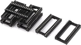
You could cut something like this to quickly test TO-220 or other types of transistors between each other. Some different Collector, Emitter, Base arrangements as well by wiring together such double row one between rows. Ofc wouldn't be perfect in terms of sound, but would save a lot of soldering and you'd still totally get the quality.
Attachments
You are one of the few who want to gain practical experience;-) Others do not test the statements of others, neither practically nor mentally;-)-;Very interesting to think about it this way. Your descriptions are good, but I'd need to listen to really put my finger on it.
There are circuits in which each half-wave has both an n-channel and a p-channel type. The tonal characters of the components remain the same in every application, in every function: it therefore have both characters in every half-wave, which homogenizes the sound. However, it also sum the modulations with each stage. The sound becomes more homogeneous, but also dirtier, greyer, duller, more overcast.
A great example is Jean Hiraga's Classe A:
4 complementary steps, of which 1, 2 can be crossed and 3, 4 can be crossed:
https://sound-au.com/tcaas/hiraga2.htm
Since I want to keep the NAD "two-stage follower", I'm thinking about installing a crossed circuit instead of the original uncrossed one.
A great example is Jean Hiraga's Classe A:
4 complementary steps, of which 1, 2 can be crossed and 3, 4 can be crossed:
https://sound-au.com/tcaas/hiraga2.htm
Since I want to keep the NAD "two-stage follower", I'm thinking about installing a crossed circuit instead of the original uncrossed one.
Hi cumbb, please note that I haven't read the whole thread, but from what I see I feel I've to congratulate you and to thank you! 🙂
I've rarely seen, if ever, a singular thread (that's, made by practically only one member) so well described, well photographed, with so many photos and also diagrams, explanations, listening impressions, useful suggestions and interesting modifications.
Really, in my humble opinion you would deserve all the possible good acceptance, and if a moderator read this (and agreed) I humbly propose this thread as a sticky thread if only for the positive example (without taking anything away from other possibly similar examples) of what and how can be done and what a single person can do.
With compliments! 😉
Finally managed to repair my right channel. But only with driver transistors. Without them my bias is at -0.333V so maybe that's why my little BD441 and BD442 kept burning. But I was unable to adjust the bias further. Got them blue trimmers so a well placed one of appropriate value may solve this, but it's kinda weird, because with driver transistors I can get the bias to stay at ~0.012V.
Compared again the original big A1186 and C2837 output transistors with BD441 and BD442 as driver transistors and it's much more fun in the bass department and a little more body everywhere VS BD441 BD442 without drivers, just as output transistors (my left channel), but the left channel has incredibly greater nuance in voices for example, the highs and the textures and microdetails are quite enchanting. Voices are much better.
Got the PEG227. Want to compare them, but first I want to play more with the transistor arrangements and maybe figure out a way to make the left channel work as a follower too and not burn. Oh and I got new BD441 442 from a different batch and they measure completely differently.
Hi @Logon, thank you very much. I appreciate this comment!
And I had a real key audio experience yesterday and today:
I now have the PNP follower running, as described earlier. The BD442 sounds black, very high resolution, smooth.
And yesterday I started testing the PNP. 7 pieces: 5 TO-220, 1 BD442 for comparison, 2 BC559C CDIL (?). And I change them and hear: all black, colorless! Not a bit of color. And: in conjunction with the BD442 as a follower, completely exhausted and stressed after 20 minutes. Almost torn, like sick.
Now I have to pass on older experiences: I had also converted from NPN SE to PNP SE a few times in the past (e.g. BD441/BD442, TIP41/TIP42) and had the experience that the PNP sounded black. At the time I thought: ok, and shrugged my shoulders. But I have never done a systematic test of many PNPs. And now this: no matter which PNP I insert: no colours, only black. And the attempts to differentiate them sonically fail, not because I don't hear any differences, but because the effort would be far too high; it's enormous stress to listen to two PNPs. The differences only refer to bigger, smaller, more or less contour, slightly brighter or darker, different grain, that sort of thing. Basically, for me this is listening without orientation, and without emotional access. The BD442 alone as a follower is like seeing under bright moonlight: everything is there, super clear, contoured, but hardly a hint of color. And when a second PNP comes into play, it's like charcoal, like a coal painting, including this coal physics, some inaudible stress, some overtones or material resonances, frequencies, something that makes it unbearable. It is like torture, comparable to EMF, whether transformer or cell phone. Like being beaten up.
Now I must point out that there are obviously different types of hearing, frequency types, vibration types - peoples. Which also complicates the discussion about audio, because we hear and perceive differently. What one person doesn't notice can do the other, like: for one person a blow to the head with a hammer only causes a head scratch, the other is in a coma;-)
So there are more experiments to be done: where to connect the ground, reverse the speaker cables - I reversed the polarity of the speakers (full range without any frequency components) yesterday: then it sounded with a slight brown tone, but without contours and space, and all PNPs were the same - and so on. An NPN follower or amplifier had always shown the color differences of further, other NPNs. These PNPs virtually rob the color:
And now I can concretise the comparison with the BD441. It was already in the filler, but not yet ready to speak. The NPN doesn't sound "dirtier" but rather earthy, loamy, lively, natural. The PNP doesn't sound alive (but also not dead) but also not artificial.
I have 20 - 30 PNPs and some p channel fets to test, including a Toshiba 2SJ74. maybe, it will be a quick affair.
Aside: Here is a link to a quick run of TO-247 n-channel MosFets - these were also hard to distinguish and almost colorless - not mentioned here - compared to the NPNs:
https://www.diyaudio.com/community/threads/burn-in-for-fresh-builds.415833/page-6#post-7759594
And now to the claimed problems of complementary transistors push pull: that already different batches of a type sound different, sometimes very different, is detectable. If NPN and PNP are now different by colored and colorless, then the pictured looks like this - with different size of the transistors(-:
(... silicon transistors)
Attachments
![DSCN0604[1].JPG](/community/data/attachments/1265/1265771-c37c9b899fc8c1ce868fdf79d0a6a527.jpg?hash=w3ybiZ_Iwc)
Last edited:
The simplest way could be a trimmer instead of the bias transistor. Set it initial 0 ohm, power the amplifier and then adjust until the 1.2 (1 stage follower) or 2,4 volt (this 2 stage follower) volts are reached (further adjusting increases the idle current, but not the idle voltage).Finally managed to repair my right channel. But only with driver transistors. Without them my bias is at -0.333V so maybe that's why my little BD441 and BD442 kept burning. But I was unable to adjust the bias further. Got them blue trimmers so a well placed one of appropriate value may solve this, but it's kinda weird, because with driver transistors I can get the bias to stay at ~0.012V.
Compared again the original big A1186 and C2837 output transistors with BD441 and BD442 as driver transistors and it's much more fun in the bass department and a little more body everywhere VS BD441 BD442 without drivers, just as output transistors (my left channel), but the left channel has incredibly greater nuance in voices for example, the highs and the textures and microdetails are quite enchanting. Voices are much better.
Got the PEG227. Want to compare them, but first I want to play more with the transistor arrangements and maybe figure out a way to make the left channel work as a follower too and not burn. Oh and I got new BD441 442 from a different batch and they measure completely differently.
Great!?Really, in my humble opinion you would deserve all the possible good acceptance, and if a moderator read this (and agreed) I humbly propose this thread as a sticky thread if only for the positive example (without taking anything away from other possibly similar examples) of what and how can be done and what a single person can do.
I'll even go one step further: a separate subforum called cumbb would be appropriate.
Apart from that, I myself am apparently too stupid to recognize the genius of cumbb's tuning measures /executions and to understand the resulting sound descriptions.
That's my pov.
Regards,
HBt.
Interesting:Oh and I got new BD441 442 from a different batch and they measure completely differently.
You can get to the bottom of this matter and examine transistors with the same name but different origins using measurement technology and compare their decisive parameters.
You have to write characteristic curves - to put it casually. This is the only way to get to the bottom of an assumption. You have to proceed analytically and methodically in a structured way. Of course, you have to know what you are doing and why you are doing it - and how to do it.
HBt.
Dear Cumbb,
at the end of your current NAD journey, could you make a complete circuit /schematic so that a graphical summary is created?
Perhaps you could also give us other hobbyists the correct sources for the right components so that we can enjoy the best possible sound.
thx,
HBt.
at the end of your current NAD journey, could you make a complete circuit /schematic so that a graphical summary is created?
Perhaps you could also give us other hobbyists the correct sources for the right components so that we can enjoy the best possible sound.
thx,
HBt.
- Home
- Amplifiers
- Solid State
- Modifying a NAD 302