I think we may need to see a schematic.2. Will cutting the tracks for that switch cut the power to the amps or the entire circuit.
EDIT: Service manual link is in post #27 and shows the schematic for all you circuit fans!
Last edited:
Well, I could do yes. But it actually quite bugs me that there’s a totally pointless position on that switch, more than it should I’m ashamed to admit! The ‘3D bass’ comes across very much as like a bass boost when in fact it’s just normal sound. Why on earth there’s even an option to disable the woofer is beyond me. It’s like taking a 3 way and unplugging the bass to save electricity or listening quietly when in fact it just ruins the experience. If at all possible I’d love to alter that switch to incorporate the new amp and ditch the no woofer mode.
There’s tons of amp boards on Ali but looking through them is a headache. It is possible to get boards that are about 10 watt and definitely ones with separate dials for bass and L/R gain levels with varying wattage. If this was paired with the decreased voltage as you say, I think it’s quite doable to limit it to safe wattage levels. Trial and error with very little error, me thinks.
I’ve had another look in the chassis and I am doubtful if the existing transformer and battery housing can be kept with the 110mm pipe in place as far as it would need to go.
I had a quick look at 12V lithium packs and this: 10Ah 20Ah 30Ah 50Ah 100Ah 12V Lithium Battery LiFePO4 Solar Battery Golf Trolley | eBay looks pretty capable.
With some chassis modifications the smallest 10Ah model could fit nicely dead centre and get out the way of the pipes. I have absolutely no idea how to charge something like this though. And the last time I checked you didn’t want to mess around with stuff like this. Kind of makes me want to find an old mobility scooter on freecycle (real shame actually as one recently came up!) just so I can have a look at the circuitry. One things for certain, a pack like that would keep us partying til the early hours if it gets a mobility scooter to the supermarket and back.
I wouldn’t actually buy something like this on AliExpress, but looking at this: New original 12V 6S1P 15000mah battery rechargeable lithium ion battery pack capacity DC 12.6v 15Ah CCTV Cam Monitor + charger|Battery Packs| - AliExpress
Would seem to suggest that one jack (male) is the output and could be wired to the 12V on the PCB, and the female is the input for the charger and could be mounted out the back of the chassis.
I’ve posted on a forum that deals specifically with circuitry and electronics as there don’t appear to be any takers here for the switch issue and I’m not brave enough to touch it without some help! I mentioned the switch and these batteries. Not sure if anyone will comment but will post back if I hear anything.
Last edited:
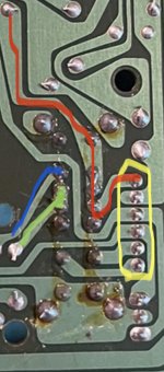
Further looking at the switch circuitry:

The yellow pins are from a connector on the reverse (top side)
The 3 top pins on the right of the switch I am guessing are either the +12V rail or ground. Could grab the meter to check this.
On the left we see what looks like 2 tracks leading off. In the top position, both are connected in the middle position, only one is connected. So the blue track is the woofer amp and the green track is the other amp.
I need to connect some earphones and see if sound can be heard via the phones port with the switch in the off position (mic on). If it can be heard, and the volume sliders still work, I reckon it’d be safe to trial cutting the tracks (as long as it’s done in a way that a blob of solder could bridge them again!
Last edited:
How else would the teenager of the day demonstrate to his/her friends what an amazing difference a 3D Subwoofer makes! 😉But it actually quite bugs me that there’s a totally pointless position on that switch ... Why on earth there’s even an option to disable the woofer is beyond me.
Haha well yes I suppose so. But it’ll be way more impressive once I’ve finished and worthy of showing off 😉
So two lots of good news this morning:
1. The headphone socket works while the speaker switch is in the ‘off’ position, which means the entire circuit is not killed.
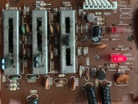
2. I have discovered the source of the hissing, it’s the graphic equaliser:

The problem with replacing this is that it powers the LEDs for the radio, but I think it should be easy enough to separate those LEDs off to a separate board. To be honest I’m not even sure if they’re worth keeping. One LED shows if FM is stereo and the other shows if LW is on.
There are 7 wires, my guess is:
2 x audio in
2 x audio out
1 x +12V
2 x ground for each LED
Could replace with this: Five-band Equalizer EQ Board 5 Band Adjustable Stereo Dual Audio Tone Board | eBay
To get 5 bands. Powers by 12V or 15V.
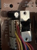
I’ve also been looking at the switch I want to adjust. It’s directly powered by the 6 pin connector next to it:

Those top 2 pins on the connector next to it (red/brown) I was expecting to find 12V… I read 60V…. 1986 efficiency. 🙂
So two lots of good news this morning:
1. The headphone socket works while the speaker switch is in the ‘off’ position, which means the entire circuit is not killed.
2. I have discovered the source of the hissing, it’s the graphic equaliser:

The problem with replacing this is that it powers the LEDs for the radio, but I think it should be easy enough to separate those LEDs off to a separate board. To be honest I’m not even sure if they’re worth keeping. One LED shows if FM is stereo and the other shows if LW is on.
There are 7 wires, my guess is:
2 x audio in
2 x audio out
1 x +12V
2 x ground for each LED
Could replace with this: Five-band Equalizer EQ Board 5 Band Adjustable Stereo Dual Audio Tone Board | eBay
To get 5 bands. Powers by 12V or 15V.
I’ve also been looking at the switch I want to adjust. It’s directly powered by the 6 pin connector next to it:

Those top 2 pins on the connector next to it (red/brown) I was expecting to find 12V… I read 60V…. 1986 efficiency. 🙂
Last edited:
Well, I could do yes. But it actually quite bugs me that there’s a totally pointless position on that switch, more than it should I’m ashamed to admit! The ‘3D bass’ comes across very much as like a bass boost when in fact it’s just normal sound. Why on earth there’s even an option to disable the woofer is beyond me.
Simple (apart from the other answer) - to save on batteries when you wanted extra life out of it.
Simple (apart from the other answer) - to save on batteries when you wanted extra life out of it.
Each to their own. I’d rather have good sound until the end than limp on for an hour longer in ‘tin mode’ 😀
Hopefully the more efficient amps and different battery will make that a non-issue.
Edit: I mean, just to clarify: without the woofer there is no bass at all. You don’t get anything through the mids. It’s a very quiet and unsatisfactory sound.
Edit2: ok, maybe if you crank the EQ right up and play something with a lot of bass it’s passable. It’s not something I would ever use.
Last edited:
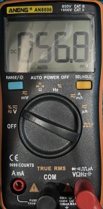
The display reads 56.8 mV (millivolts) - tantamount to zero volts!Pretty much yeah
😱 you see this is why I love having you cast a critical eye over my amateur tinkering!
Yes you are right. Correct value is ~6.5V on both the red and brown wires. I wrongly assumed red was positive and brown was ground as this is the colouring that is used on the 2 pin cable that feeds the 12V to the board. I didn’t even notice the mV on the display.
So both are in fact +6.5V with a discrepancy of ~60mV. 😱
This shouldn’t affect the plan for the switch though.
"Tinkering"? Is that what you call it?
I would call it "major surgery".
I hope the patient survives! 😀
I would call it "major surgery".
I hope the patient survives! 😀
I would call it "major surgery".
Butchery more like.😱😀
You do know these vintage ghetto blasters fetch very decent money in unadulterated (but working) form ?............
😀 well if the patient doesn’t survive, it’s been fun. If the patient does survive, it’ll be something for my kids to show their friends at birthday parties! 😉
@MikePP yeah but this one was already battered. It’s got a faulty EQ, dents and scratches all over it, the battery cover is missing, the radio antenna is snapped out the back leaving a huge hole, there screws and rubber feet missing, the grilles are dented with flecks of paint missing, the handle is dodgy etc. There’s one in better condition for £60 on eBay. There’s also a mint one for £280, but we’re miles from that! I paid nothing for it, so butchery it is. 🙂
@MikePP yeah but this one was already battered. It’s got a faulty EQ, dents and scratches all over it, the battery cover is missing, the radio antenna is snapped out the back leaving a huge hole, there screws and rubber feet missing, the grilles are dented with flecks of paint missing, the handle is dodgy etc. There’s one in better condition for £60 on eBay. There’s also a mint one for £280, but we’re miles from that! I paid nothing for it, so butchery it is. 🙂
Last edited:
I don’t know why I do this to myself but….
Someone has put the idea in my head that a 4 line display would go marvellously on the top of this. I’m inclined to agree. But I won’t get into that right now, what I do need some help with is figuring out this:


The above is the graphic equaliser board.
Circuits like this make my eyes glaze over. I need to figure out the pins.
So far I have:
1. Ground - Right Channel?
2. Ground - FM stereo indicator LED
3. +5.2V
4. Ground - Left Channel?
5. Positive - Left Channel?
6. Positive - Right Channel?
7. Ground
Is anyone with a more circuity background able to confirm if this is correct?
Someone has put the idea in my head that a 4 line display would go marvellously on the top of this. I’m inclined to agree. But I won’t get into that right now, what I do need some help with is figuring out this:


The above is the graphic equaliser board.
Circuits like this make my eyes glaze over. I need to figure out the pins.
So far I have:
1. Ground - Right Channel?
2. Ground - FM stereo indicator LED
3. +5.2V
4. Ground - Left Channel?
5. Positive - Left Channel?
6. Positive - Right Channel?
7. Ground
Is anyone with a more circuity background able to confirm if this is correct?
The pins of what ?? - the power output chip (IC501) ? or the board interconnecting pins?
. I’ve just spent 30 mins following lines.
That's basically what you have to do when tracing out where wire/signals go in circ diags 😛🙂
Then for good measure, you double check that you have followed it correctly
Board interconnecting pins.
To clarify: on CN501/P501 ?
Sorry you have to be precise when talking about a circ diag.....
What you need is a reverse engineering team! 😀Is anyone with a more circuity background able to confirm if this is correct?
Attachments
- Home
- Source & Line
- Analogue Source
- Modifying a Hitachi TRK-3D8E.. Ideas?


