Have traced S502:

Edit: R416 leads to P403 pin 1, microphone
@MikePP at the moment the switch functions in the 3 positions:
502-1. Woofer on, left/right (inc headphone socket) on
502-2. left/right (inc headphone socket) on
502-3. Woofer off, left/right (inc headphone socket) off, microphone on
Edit: I think these are the correct designations
My plans for this switch are to cut the tracks for positions 1 and 2 and use them to ground or connect 2 low power TPA based amps that I have ordered. The switch should function like this:
502-1. Both TPA amps powered
502-2. Only 1 TPA amp powered
502-3. Neither TPA amp powered, microphone on
For this to actually be viable I will need to power down the IC501 and IC502 amps, as they seem to be powered all the time and 2 useless amps does not a good runtime make. What I am unsure about and perhaps you will be able to shed some light on is:
1. Do these amps just power the drivers or will disconnecting them affect the tape decks, radio, microphone and line in? I am thinking [and hoping!] not because on page 12 there seem to be preamps for the tape decks, Q401R and Q401L and for the microphone and line in, IC451? For the radio there appears to be Q101 and Q151 on page 10.
2. And probably a more important question, will this switch actually be able to take several amps of DC voltage? Is there anything in the service manual that you can see that would suggest it is capable of this? Or any ideas on how I could check what it’s capable of short of dumping current through it and hoping it doesn’t melt? 😱
Last edited:
What I often do if I'm repurposing (or overriding the tarnished contacts) orignal (and unobtanium) switches is to dis them from the original circuit by cutting tracks, then rigging up small signal relays that are switched/controlled by the original switch. i.e. you're just switching the relay control voltage throught the switch and letting the relays do all the heavy lifting .
- Be warned you must absolutely clear which is the common.wiper and which are the contacts before continuing otherwise you'll end up in a right muddle and be extremely frustrated.
What I often do if I'm repurposing (or overriding the tarnished contacts) orignal (and unobtanium) switches is to dis them from the original circuit by cutting tracks, then rigging up small signal relays that are switched/controlled by the original switch. i.e. you're just switching the relay control voltage throught the switch and letting the relays do all the heavy lifting .
Ahh yes that seems like a very sensible idea.
Something like this?
10PCS Smart Electronics New Original Solid State Relay G3MB 202P DC AC PCB SSR In 5VDC,Out 240V AC 2A|Relays| - AliExpress
AC amps are not the same as DC amps so the rating on then switched side should be sufficient? I chose solid state so it’s quiet… although I’m not so sure.. maybe the clicking will add to the charm 😀
- Be warned you must absolutely clear which is the common.wiper and which are the contacts before continuing otherwise you'll end up in a right muddle and be extremely frustrated.
Yeah this hasn’t been low frustration to this point, maybe this would be a better approach:

I can verify what we’ve found without any interference from the PCB. Not sure if I could tell you what shape the wiper is, but I will be able to confirm by systematically running through each pin and checking against every other pin.
Or it could be "goodnight Vienna"! 😀
Yeah that would suck. No other way to say it! Still gotta figure out some kind of battery alteration down the line - whether it’s keeping the Ds or using something else, the current layout internally is not compatible with the pipes so it’ll have to change 😱
Just think, if we get this done in time for December, it could liven up our drunken Christmas parties in the woods… like this guy: Dubstep Santa - YouTube
(Sorry is that last bit too much?) 😀
You're buying cheap junk again of dubious provenance from a mostly dodgy site 🙄😉
Pick whatever voltage you want (depending on where you're drawing the supply from)
You also need to watch the total current draw of these relays (with all on worse case scenario) whichever supply you steal the power from..... or fit a small toroid to supply just these relays.
Also don't forget a protection diode across each and every one of them. 😱🙂
if we get this done in time for December,

You're buying cheap junk again of dubious provenance from a mostly dodgy site 🙄😉
There’s lots of great things on AliExpress.. like ESP32 modules and Arduino clones but if you think the relays are a bad idea I’ll get them from CPC.
Pick whatever voltage you want (depending on where you're drawing the supply from)
I was going to draw the voltage directly from the PSU or batteries (with a fuse on the positive wire), not from the existing PCB.
Batteries/PSU > Power Switch > Fuses > Arduino/Relays. I’ll draw out a circuit soon and post it.
You also need to watch the total current draw of these relays (with all on worse case scenario) whichever supply you steal the power from..... or fit a small toroid to supply just these relays.
I have a 12V 8A PSU that I was going to initially hook things up to then measure the current draw with the clamp meter.
Also don't forget a protection diode across each and every one of them. 😱🙂
Are you able to recommend something suitable?
There’s lots of great things on AliExpress.. like ESP32 modules and Arduino clones?
Yes ..... assembled modules (I buy from there sometimes for modules or 'things'), but components ?........... it's a no from me
but if you think the relays are a bad idea I’ll get them from CPC.
It's the same thing ultimately .... that power is coming from the PSU either way...I was going to draw the voltage directly from the PSU or batteries (with a fuse on the positive wire), not from the existing PCB.
The product's PSU was designed with a certain topology in mind with a little overhead/margin.
The more stuff you add, the more you eat into that design overhead/margin, something will give way unless you are conscious of what you are adding and taking away at every stage.
Yes, read up about relays and what you have to add into the circuit when using them.. for this level of relay a 4148 or 4001 is just finerecommend something suitable?
Don't mind helping but I'm not spoonfeeding you each step cos you'll not take on any education 🙂
Last edited:
Ok no problem. I’ll go away and see what I can come up with and post back when I have something.
Just to clarify on the PSU, I am not talking about using the product’s original PSU. I have an external ‘laptop style’ brick that outputs 12V 8A, and I roughly calculated:
- original PCB with IC501 and IC502 disconnected: 25W-14W / 12V = 1A
- Arduino: 0.5A
- Amp 1 - L/R + Woofer: 14W / 12V = 1.2A
- Amp 2 (not higher than 40W - probably less, need to test): 40W / 12V = 3.34A
- EQ: 0.5A
- ~10% overhead: 0.7A
Total: 7.3A
Totally understand not wanting to spoon feed and I agree. I am a practical learner which makes reading blocks of text rather difficult, show me once and I retain it. But trying to create a set of actions from a description is difficult for me and I do appreciate your patience. 🙂

Right…. Here’s what we have so far. This is work in progress but I wanted to show what we’ve been up to 🙂
Here are the main changes and additions:

And here is more detail on the switch leading from the line in:

If you can see dark lines on the reverse, it’s because we borrowed an old Disney princess art pad ;-)
What do you think?
Here are the main changes and additions:
And here is more detail on the switch leading from the line in:
If you can see dark lines on the reverse, it’s because we borrowed an old Disney princess art pad ;-)
What do you think?
What do you think?

You've completely misunderstood the use of the relays !!
The original switches should be supplying the coil of the relays (either ground or the supply) to subsequently switch the load (the amplifier output ..... or supply - your choice)
But you created a very wacky circuit there, feeding the TPA + supply? through the coil of the relay.
(I take it the TPA + and - shown are the supply connections and not the outputs?, not that it makes much difference - you need to go back to the drawing board - big style - sorry ......
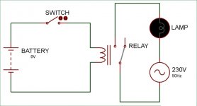
Take a look at a simple relay circuit, note the 9volts on the relay coil side will (can) if needed switch 230V (mains) on the contact side - it could be anything on the contacts side depending on the relay chosen: mains , 25V , a speaker output , a speaker ground , both !
but the lowly 9V (in this case) through the measly switch controls the relay, which actually does the switching.
Attachments
Last edited:
Argh! This is a diagram error!
Does this look better?

Edit: actually, no it doesn’t, the diode needs to move to the coil side. Hang on changing.
Does this look better?
Edit: actually, no it doesn’t, the diode needs to move to the coil side. Hang on changing.
Last edited:
Only slightly lol
You've got the protection diodes across the relays contacts..😱
Redraw the whole thing (or edit it) and repost it
and change the + to Vcc and the -'s to 0V or similar instead of + and - everywhere, it's easier to read.....
But don't call different voltages all Vcc, differentiate them.
You've got the protection diodes across the relays contacts..😱
Redraw the whole thing (or edit it) and repost it
and change the + to Vcc and the -'s to 0V or similar instead of + and - everywhere, it's easier to read.....
But don't call different voltages all Vcc, differentiate them.
Last edited:
And no need for lights on the Christmas tree or a log fire to keep you warm! 😀Just think, if we get this done in time for December, it could liven up our drunken Christmas parties in the woods.
And no need for lights on the Christmas tree or a log fire to keep you warm! 😀
Not sure if a portable reactor number 4 is what I had in mind for this, but at this rate who knows :-S
Redraw the whole thing (or edit it) and repost it
and change the + to Vcc and the -'s to 0V or similar instead of + and - everywhere, it's easier to read.....
But don't call different voltages all Vcc, differentiate them.
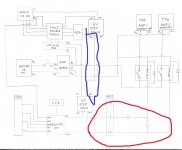
How’s this?

Blue circle - take another look and spot the mistake and correct.
You're doing right by doing hump back bridges for crossing over wires, but for deliberate connections of crossing wires you should be putting a bold 'full stop' at the connection, so everyone knows they're connected , at first glance it looks like the Vcc suuply doesn't feed either of these 5v step downs
Red circle - take another look at this diode configuration and correct. (although I'm not sure what you're trying to achieve in this area anyway)
Attachments
Last edited:
With the diodes after S502, I was not sure about them. The purpose would be to stop the -1 relay energising when the switch is in position -2, else there’s no point in the switch (but we want -2 to energise when in position -1). Looking at it again, it seems like the diode after -2 is probably useless so I have removed it.
In the blue circle, did you mean the error is the dots signifying a connection? If so how’s this:

Please excuse the crappy colour on the right and any artefacts. Im having to take a photo on my phone in artificial light and bump the exposure.
I didn’t realise it was good practice to use both the humps and the bold dots. A lot of things I’ve seen use either one or the other.
If there’s something else in that blue circle, I’m not seeing it right now. I’ll have to look at it tomorrow after coffee. It does look messy though, could do with an untangle.
Edit: I’ll add labels for diodes and relays (part numbers) tomorrow as well.
In the blue circle, did you mean the error is the dots signifying a connection? If so how’s this:
Please excuse the crappy colour on the right and any artefacts. Im having to take a photo on my phone in artificial light and bump the exposure.
I didn’t realise it was good practice to use both the humps and the bold dots. A lot of things I’ve seen use either one or the other.
If there’s something else in that blue circle, I’m not seeing it right now. I’ll have to look at it tomorrow after coffee. It does look messy though, could do with an untangle.
Edit: I’ll add labels for diodes and relays (part numbers) tomorrow as well.
Last edited:
I’ve looked through the relays on CPC this morning and this one looks like it will do the job nicely: https://www.farnell.com/datasheets/1537833.pdf
Specifically the ALDP105.
It has a small form factor and it’s contact rating is 5A.
Specifically the ALDP105.
It has a small form factor and it’s contact rating is 5A.
Last edited:
- Home
- Source & Line
- Analogue Source
- Modifying a Hitachi TRK-3D8E.. Ideas?