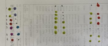
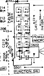
Yes that’s correct CN501/PN501.
What I need is to not ‘tinker’ 😛
What you need is a reverse engineering team! 😀
What I need is to not ‘tinker’ 😛
Last edited:
So far I have:
1. Ground - Right Channel? Nope
2. Ground - FM stereo indicator LED - this isn't the ground as such , it's how you turn the stereo indicator on, by grounding it
3. +5.2V - B+ - if that's 5v in this product then yes
4. Ground - Left Channel? nope
5. Positive - Left Channel? nope
6. Positive - Right Channel? nope
7. Ground - hurrah
The more you do yourself the more you'll understand , so try again.
You've not helped by splitting the pages into two pics, it's hard to follow on this side of the screen
Get more of the circuit into one page/pic , but don't make it miniscule.
Another tip: most circuit diag (sections) go/(electrically flow signal wise) from left to right on the page , so that might give you an idea where inputs and outputs are in the circuit.
Get more of the circuit into one page/pic , but don't make it miniscule.
Another tip: most circuit diag (sections) go/(electrically flow signal wise) from left to right on the page , so that might give you an idea where inputs and outputs are in the circuit.
Last edited:
Haha, wow I rocked that.
Ok I will try again. In my defence the PDF is split up into pages like that. I have found it very difficult to follow. I’ll have one more look but perhaps twenty to eleven at night isn’t the best time.
Ok I will try again. In my defence the PDF is split up into pages like that. I have found it very difficult to follow. I’ll have one more look but perhaps twenty to eleven at night isn’t the best time.
1. Output - Right
2. FM LED - cathode
3. +5.2V / B+
4. Output - Left
5. Input - Left
6. Input - Right
7. Ground
2. FM LED - cathode
3. +5.2V / B+
4. Output - Left
5. Input - Left
6. Input - Right
7. Ground
1. Output - Right
2. FM LED - cathode
3. +5.2V / B+
4. Output - Left
5. Input - Left
6. Input - Right
7. Ground

In my defence the PDF is split up into pages like that. I have found it very difficult to follow.
https://www.vintageshifi.com/repert....php?pdf=Hitachi-TRK-3-D-8-Service-Manual.pdf
The switch looks like a multi 4-position (pole) one , quite common, you'll see it's various 4pole sections spread about the circuit diagram listed as s501-1, s501-2 etc etc
Look on page 10 for switch section number one: S501-1
and then meter out the switch at one end (continuity to determine wheich end of the switch is the -1 group of contacts..
(i.e. match the switch to the circuit)
So each group has a wiper and four associated contacts (some contacts aren't used in each group)
Last edited:
I would strengthen the plastic walls.
Hi 🙂 good suggestion. What would you use to reinforce them? The end pieces will be reinforced with MDF because I will need to build a small internal structure to support the drain pipe. Would you say Perspex sheet cut and glued into place would be acceptable?
https://www.vintageshifi.com/repert....php?pdf=Hitachi-TRK-3-D-8-Service-Manual.pdf
The switch looks like a multi 4-position (pole) one , quite common, you'll see it's various 4pole sections spread about the circuit diagram listed as s501-1, s501-2 etc etc
Look on page 10 for switch section number one: S501-1
and then meter out the switch at one end (continuity to determine wheich end of the switch is the -1 group of contacts..
(i.e. match the switch to the circuit)
So each group has a wiper and four associated contacts (some contacts aren't used in each group)
I finally had time to look at this a bit this morning and it was a rather unproductive time. 🙁
Apart from figuring out which of the contacts on S501 ‘might’ be ground, I’ve managed to accomplish nothing. I took a break from that and decided to look again at S502, and I think there’s a high likelihood I have that wrong too.
I initially thought that S502 cut the power to each amp but I’m not so sure. The contacts for S502 are directly linked to P502 and P503, which are the connectors that feed the headphone jack and drivers. So I’m guessing that all the switch does is disconnect the drivers but the amps remain powered on!! This is totally incompatible with the plans I had not to mention a hideous waste of power.
Going to go and eat a crisp sandwich now because my head hurts.
 Will revisit again soon.
I finally had time to look at this a bit this morning and it was a rather unproductive time. 🙁
Apart from figuring out which of the contacts on S501 ‘might’ be ground, I’ve managed to accomplish nothing. I took a break from that and decided to look again at S502, and I think there’s a high likelihood I have that wrong too.
I initially thought that S502 cut the power to each amp but I’m not so sure. The contacts for S502 are directly linked to P502 and P503, which are the connectors that feed the headphone jack and drivers. So I’m guessing that all the switch does is disconnect the drivers but the amps remain powered on!! This is totally incompatible with the plans I had not to mention a hideous waste of power..
On these two multi switches (501 and 502) you’re not looking for a ground per se , you’re looking for a common wiper and then in the case of 501 there’s four contacts and in the case of 502 there’s three contacts.
Clearly ID the wiper with multimeter (testing at different switch positions) and the same pattern runs up the entire switch with each switch sub-group….
Once you know that You can repurpose switch groups for your own purposes. Cutting tracks or using unused switch groups.
The four groups of 502 just disconnects the outputs and also one group grounds the mic input.
Last edited:
Ok got it. Off to the in laws today for lunch/dinner but will post back again as soon as I have had another look. 

Right. I’ve had another look this morning and I’m not sure if I’m any further along but this is what I’ve managed to do with S502 (3D switch).
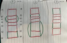
With the meter on continuity and the switch in the 3 positions, I checked for continuity between each of the pins. The following are the pins that seem to be connected in each position (same colour = continuity):

Left is the 3rd position (down) where the microphone is connected
Middle is the 2nd position (middle) where just the L/R drivers are connected
Right is the 1st position (up) where all drivers are connected
In the 1st position (right) it looks like there’s 2 distinct groups of contacts, each touching 3 pins, but then I’m really not sure what I did wrong in the middle position - probably continuity from the tracks on the board and the rest of the circuit, the drivers are unplugged but this would be easier if the switch was removed. Not sure where to go from here?
With the meter on continuity and the switch in the 3 positions, I checked for continuity between each of the pins. The following are the pins that seem to be connected in each position (same colour = continuity):

Left is the 3rd position (down) where the microphone is connected
Middle is the 2nd position (middle) where just the L/R drivers are connected
Right is the 1st position (up) where all drivers are connected
In the 1st position (right) it looks like there’s 2 distinct groups of contacts, each touching 3 pins, but then I’m really not sure what I did wrong in the middle position - probably continuity from the tracks on the board and the rest of the circuit, the drivers are unplugged but this would be easier if the switch was removed. Not sure where to go from here?
Right. I’ve had another look this morning and I’m not sure if I’m any further along but this is what I’ve managed to do with S502 (3D switch).
With the meter on continuity and the switch in the 3 positions, I checked for continuity between each of the pins. The following are the pins that seem to be connected in each position (same colour = continuity):
View attachment 989322
Left is the 3rd position (down) where the microphone is connected
Middle is the 2nd position (middle) where just the L/R drivers are connected
Right is the 1st position (up) where all drivers are connected
In the 1st position (right) it looks like there’s 2 distinct groups of contacts, each touching 3 pins, but then I’m really not sure what I did wrong in the middle position - probably continuity from the tracks on the board and the rest of the circuit, the drivers are unplugged but this would be easier if the switch was removed. Not sure where to go from here?
The post doesn't make sense 😕, more so when you look at the diagram 😛
I'm not you have just yet , just study any (or a couple) switch groups (from the same switch obviously - 501 or 502)Ok got it.
In the case of the 502 switch either the -1 or to -4 bank is easier first (this is because it's the bank that's at either end of the physical switch...)
Then identify the wiper (or common), and then you can identify the poles for that wiper/common.
I can't help because I can't see the track layout clearly from that murky pdf scan, nor what you want to do with the switch
Not a problem, and thanks for bearing with me. I’ll have more time to look again tomorrow. I’m determined to get this 😀
Dave, I've just been listening to Midge Ure utter these immortal words:
This means nothing to me
This means nothing to me
Oh, Vienna
😀
This means nothing to me
This means nothing to me
Oh, Vienna
😀
Until this morning, it meant nothing to me too!
But I’m quite stubborn and determined this is going to happen. The Mrs has been drawing sketches of the artwork plans so is fairly set on this as well. She is very good at logic puzzles so with her help we got the above. It shows what pins are connected in each switch position. With this, we can hopefully figure out:
With 501: which pins contain 5 volts only when the switch is in a certain position
With 502: which tracks to cut to repurpose the switch to power our own 2 amps
Will also need to figure out how to cut power to the on board amps as they’ll be useless.
The next bit will be seeing on 502 where each of those pins go to and checking if they can be disconnected. On 501, I’ll have to power up the board and check for 5 volts on each connected pin in it’s respective switch position. The Arduino has 6 pins that can detect 5 volts and use this to display text on the LCD, “Tape”, “Aux” etc.
Still entirely possible that something will go pop when I do this.. I don’t pretend to know too much about what I’m doing with this 😱
- Home
- Source & Line
- Analogue Source
- Modifying a Hitachi TRK-3D8E.. Ideas?


