Then the factors you have to consider are impedance and sensitivity as mentioned above.
And, whether it is the bass or mid/high range you seek to augment.
And, whether it is the bass or mid/high range you seek to augment.
I've just seen this.Would it be a totally insane idea to locate on the PCB where the signal goes to the amplifiers and feed a separate TPA3118 to full rangers enclosed in PVC tube? Could add an additional switch to turn the TPA3118 on/off for “Classic Mode” and “Super Mega Awesome Improved 4D Mode” 😎
The challenge would be in selecting the appropriate full range driver to suit the volume of one of your new internal sealed enclosures.
If you measure up the volume available to each full ranger (while leaving sufficient volume for the existing woofer) and state the diameter that said full ranger would have to be, then I'm sure someone would recommend a suitable driver.
As for the PCB query, have you access to the circuit diagram yet?
while leaving sufficient volume for the existing woofer
So correct me if I am wrong, but each end of that enclosure (the entire boom box) is vented - see one of the first pictures with tape measure. In fact, it’s not sealed at all in many places. I don’t pretend to know much about VAS and it’s relationship with drivers but I would guess that the existing drivers don’t require a fixed amount of space, else greater effort to ‘seal them into’ the enclosure would have been taken.
state the diameter that said full ranger would have to be, then I'm sure someone would recommend a suitable driver.
This I’ll have to work out. I definitely think gutter down pipe (whatever size that is) would fit in there. It’s entirely possible something larger but may have to look at externalising the PSU and changing the batteries. Something I had considered anyway. Another option is to heat and ‘bend’ the pipe around the components or construct an odd shaped enclosure from Perspex. If using pipe, I reckon the maximum diameter will be about 85mm. These for example: 20W 3 Inch Speaker 4~8 Ohm Full Frequency Speaker 1 Pcs Fever HIFI Metal Ceramic Aluminum Basin Home Audio Amplifier Speaker|Bookshelf Speakers| - AliExpress might go well, they only require 1.37L each. They only require a 71mm diameter enclosure, which helps. Here’s a question… how close to 1.37L does that have to be?
As for the PCB query, have you access to the circuit diagram yet?
No… Do such things even exist outside of Hitachi HQ? I thought it might be possible to guess and confirm with a multimeter 😀
So wait… this idea isn’t all that bad? 😱
This should run whatever it is nicely: TPA3110 XH A232 30W+30W 2.0 Channel Digital Stereo Audio Power Amplifier Board DC 8 26V 3A C6 001|Operational Amplifier Chips| - AliExpress
I realise that the existing cabinet is ventilated (rather than "vented" which has a particular acoustic meaning).
For quality secondary reproduction, you should consider full range drivers that are acoustically loaded to small sealed enclosures.
I gave you one link to the Service Manual. You have to pay for a full download. Look around for alternative sources.
For quality secondary reproduction, you should consider full range drivers that are acoustically loaded to small sealed enclosures.
I gave you one link to the Service Manual. You have to pay for a full download. Look around for alternative sources.
I didn’t realise vented was a term used for something else! I’ll try to remember that.
I think I found it 😉 View attachment hfe_hitachi_trk-3d8_service 2.pdf
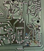
Looks like literally the output of the volume sliders is a good place:

Should be easy to find on the reverse and solder to.
Also looks like the mids and tweeters aren’t filtered??
I think I found it 😉 View attachment hfe_hitachi_trk-3d8_service 2.pdf
Looks like literally the output of the volume sliders is a good place:
Should be easy to find on the reverse and solder to.
Also looks like the mids and tweeters aren’t filtered??
Vented refers to a ported (tuned) enclosure.
You have located a suitable point for signal extraction.
You have located a suitable point for signal extraction.
They are not high pass filtered. The stereo amp itself may be bandwidth limited as I said earlier so that little low bass is supplied to the mids.
Ok so next part is to see how much space I can really squeeze out of that enclosure.
I’ve been thinking about batteries. Total voltage is 12V using 8 x 1.5V Size D cells, my initial thought was that lithium was the way to go but it may well be that WhiteDragon is right about sticking with D cells but I am not sure about the total voltage, being 0.3V less for rechargables per cell. You can easily get 2600mAh and 4.2V out of a single 18650, so 3 x 18650 would be 12V @ 2600mAH, 6 x would be 4200mAh, 12 x would be 8400mAh? (Sorry it’s late might be making really obvious crappy errors here). I thought this would be greater than size D cells but: Amazon Basics D Cell Rechargeable Batteries 10000mAh Ni-MH, 4-Pack (Appearance may vary): Amazon.co.uk: Electronics & Photo
Are cells like this total junk? Seems like using 8 of these will give 9.6V and 10,000mAh not sure if that loss of 2 volts will matter.
9.6V @ 10,000mAh vs 12.6V @ 8400mAh
We used to have an ion block rocker that ran on a motorbike battery.. the sound sucked so we got rid of it, but the lead battery was an interesting idea. Plenty of mAh in that…
Non-rechargeable D cells have an emf of 1.5V, but the voltage available to the circuit drops below that value in use due to the high internal resistance of these cells.
Rechargeable D cells have an emf of 1.2V, but this volage is maintained in use due to the low internal resistance of these cells.
The rechargeables are therefore compatible in terms of your requirements.
Rechargeable D cells have an emf of 1.2V, but this volage is maintained in use due to the low internal resistance of these cells.
The rechargeables are therefore compatible in terms of your requirements.
Gotcha, thanks!
So we’ve had a look and have been working out what we can actually squeeze out of the internals. The answer is 0.7L if using pipe…. and the PSU would have to go…. And they would be off centre 🙁 The TRK-3D75E has external enclosures for a reason!
“That’s crap!” I hear you shout? Well yes it is. So we’ve been brainstorming….. And I must say I’m feeling really quite pleased with myself!
Drum roll…..


Should be easy to Dremel a hole in the end covers and glue that in there. Drivers face out (obviously) and the junction facing up can either have some switches on it or one of these:

Now I need to figure out what the ID of something like that is and how much VAS it will give. Might be easier to go to Plumb Base.
So we’ve had a look and have been working out what we can actually squeeze out of the internals. The answer is 0.7L if using pipe…. and the PSU would have to go…. And they would be off centre 🙁 The TRK-3D75E has external enclosures for a reason!
“That’s crap!” I hear you shout? Well yes it is. So we’ve been brainstorming….. And I must say I’m feeling really quite pleased with myself!
Drum roll…..
Should be easy to Dremel a hole in the end covers and glue that in there. Drivers face out (obviously) and the junction facing up can either have some switches on it or one of these:
Now I need to figure out what the ID of something like that is and how much VAS it will give. Might be easier to go to Plumb Base.
Drainage pipe?
I hope this project is not going down the drain! 😀
P.S. Vas is not the required volume of the driver enclosure, but is a T/S parameter that is used, along with the other parameters of the driver, to calculate the required volume.
The experts on the 'Full Range' speaker sub forum have software to match enclosure to driver and you could ask for help over there.
Ahh, didn’t know that. Now I do 🙂 I’ll work out what size driver I need then head over.
As for it going down the drain, it’s going to look one of two ways… !!
As for it going down the drain, it’s going to look one of two ways… !!
Got pipe?
View attachment 987814
It was easier to fill it up with water than work out the area…
View attachment 987815
It is 3L total.
But I will need to cut off about 1-1.5cm from the driver and top opening because otherwise it won’t look like a Mario pipe. Then after gluing a plastic disk in there to mount the driver, I think it’s realistic to take 3.5cm off it. So about .3L loss on that end. 0.1L loss on the top facing end, and nothing on the internal end. So total loss about 0.4L so 2.6L usable before driver… this could be tight.
Last edited:
A Peerless 830987 3" full range in an approximately 2.5 L sealed enclosure will do the job.
See other thread!
See other thread!


Next problem.
This switch:

Is THE MOST RIDICULOUS thing I have ever seen. In the top position, both the mids/tweeters and woofer are on. Or what you may call ‘Normal’ sound. In the middle position, the woofer amp is turned off leaving what can only be described as the worst awful tinny experience that no one is EVER going to use. The bottom position is both amps off and mic on
On the reverse we see that it appears that the switch bridges 2 sets of pins per side in each position:

I am seriously considering buying a second TPA amp board like this: £9.29 15% Off | AIYIMA TDA7377 2.1 Amplifier Board 20W*2+30W Hifi Subwoofer Amplifiers With Tone Volume Adjustment For Bookshelf Speaker DIY
AIYIMA TDA7377 2.1 Amplifier Board 20W*2+30W Hifi Subwoofer Amplifiers With Tone Volume Adjustment For Bookshelf Speaker DIY|Amplifier| - AliExpress
Then hooking the existing speakers and woofer to it, and the new full rangers to the other amp then cutting the tracks on the top 2 positions on the switch and rewiring so it’s:
Top position: both amps on
Middle position only original drivers amp on
Bottom: unchanged
This would completely bypass the original amplifiers.
Things I am unsure about:
1. Will the replacement TPA amp board be suitable for the original 3 drivers
2. Will cutting the tracks for that switch cut the power to the amps or the entire circuit
I am hoping that this will also prove to be more energy efficient, and possibly sound better.
If there’s anyone here who knows more about this type of PCB or is able to follow the tracks a bit better I would welcome any pointers.
This switch:
Is THE MOST RIDICULOUS thing I have ever seen. In the top position, both the mids/tweeters and woofer are on. Or what you may call ‘Normal’ sound. In the middle position, the woofer amp is turned off leaving what can only be described as the worst awful tinny experience that no one is EVER going to use. The bottom position is both amps off and mic on
On the reverse we see that it appears that the switch bridges 2 sets of pins per side in each position:
I am seriously considering buying a second TPA amp board like this: £9.29 15% Off | AIYIMA TDA7377 2.1 Amplifier Board 20W*2+30W Hifi Subwoofer Amplifiers With Tone Volume Adjustment For Bookshelf Speaker DIY
AIYIMA TDA7377 2.1 Amplifier Board 20W*2+30W Hifi Subwoofer Amplifiers With Tone Volume Adjustment For Bookshelf Speaker DIY|Amplifier| - AliExpress
Then hooking the existing speakers and woofer to it, and the new full rangers to the other amp then cutting the tracks on the top 2 positions on the switch and rewiring so it’s:
Top position: both amps on
Middle position only original drivers amp on
Bottom: unchanged
This would completely bypass the original amplifiers.
Things I am unsure about:
1. Will the replacement TPA amp board be suitable for the original 3 drivers
2. Will cutting the tracks for that switch cut the power to the amps or the entire circuit
I am hoping that this will also prove to be more energy efficient, and possibly sound better.
If there’s anyone here who knows more about this type of PCB or is able to follow the tracks a bit better I would welcome any pointers.
Attachments
1. Will the replacement TPA amp board be suitable for the original 3 drivers.
The existing drivers may have too small a power handling capacity for your chosen amplifier. 1 x 30 W and 2 x 20 W is claimed. However there's no indication that those are 'real' RMS figures so you might just get away with it! In addition, your use of a 12 V power supply will ensure the power output is much lower than the quoted figures.The 8 ohm superwoofer is driven by a mono 8 W amplifier. The 4 ohm mids are driven by a 2 x 3 W stereo amplifier.
The total power rating is 14 W RMS @ 10% distortion.
Personally, I would keep the existing amplifier/driver configuration, which is true to the original boombox conception, and concentrate on the supplementary driver/amplifier idea. But it's your project! 😉
Last edited:
- Home
- Source & Line
- Analogue Source
- Modifying a Hitachi TRK-3D8E.. Ideas?