in this case....the power supply caps are connected through the -4 volt regulator....If you used a BJT in the place I would agree with you...but as you here have a fairly big over voltage..There's no need for big cap.s
This with the modulated GND.. is why you need big caps and why quality really matters..this to an extent where they are as important as the circuit...maybe even more...as they are right in the signal path...
This amplifier is not normal.....as the speaker GND is regulated....and the other end of the power supply is shielded by a current source with Mega ohm isolation....an efficient way to take it out of the loop....or at least greatly to reduce the influence....
Drawback is the limited output swing of app +/- 20 V and the total current limitation to the little under 4 Amps...
In dreams, I would use Black Gate NX - series, 1000uF x 36pcs (or Similar Elna Cerafine).
Actually, I managed to have only a bag of Jamicon WG 680uFx63V, and use 36pcs of them per channel, and a shunt consisting of 2pcs of Mundorf 68uFx400V polypropylene caps. With these values and numbers, I measured impedance module vs frequency in double logariphmic scale, and I did not observe specific resonant small deeps or bumps. I had only one quite flat and wide deep in 3-10 kHz region, with characteristic impedance growth to the left and to the right from it.
Looking datasheets of other manufacturers (Panasonic, SamWha, Rubycon etc.) one can see that all of them have low-esr computer boards intended caps, with dielectric losses specified at 100kHz. Panasonic and SamWha even better than Jamicon.
I can foresee objections again a cluster of small caps, because of bigger parasitic inductance induced by assembling structure. One must not be afraid of this parasitic inductance, copper wire itself does not bring too much injury to sound. On the other hand, a kind of injury caused by big electrolytics is not studied in detail (soundwise), but this injury is unnatural and unpleasant, sound becomes "dark" and "plain".
Thank you for this information - next days I will check various datasheets of small caps like the mentioned above.
MiiB,
Devices don`t care what you label as ground.....
The speaker currents will inevitably modulate it....
All amplifiers are normal in this respect, also this one, it has nothing to do with power supply....!!
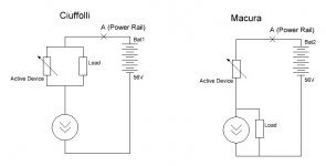
Please, compare the enclosed two schematics, think about what happens with current at the point A while the "potentiometer" (it is active device) changes its resistance.
Also think, what happens to active device when the load is short circuted, in these two schematics versions. This specifity of Ciuffolli's schematics saved me, when I did the burning-in with short circuted speaker cable.
Attachments
Last edited:
Works exactly like my Current diversion filters in my loudspeakers....🙂
I guess you are lucky with your speakers. I am getting more and more confirmations, that good sound likes shunt-kind schematics, either output stage like this follower, or shunt power supply, or shunt-like speaker filter ...
MiiB,
the task of the power supply capacitor is complex and demanding, much more than that of the DC blocking cap.
Depending on topology, speaker return currents entering the amplifier cause significant distortion. It can be reduced by approaching the ideal amplifier output impedance that is infinite. A higher impedance greatly improves speaker linearity as well.
WuYit
but current amplifiers can't be used with all kind of loudspeakers as current sources counteracts the way normal loudspeaker filters work...This particular amplifiers is neither....it's a voltage controlled current source...
but current amplifiers can't be used with all kind of loudspeakers as current sources counteracts the way normal loudspeaker filters work...This particular amplifiers is neither....it's a voltage controlled current source...
MiiB,
right, in the bass range you will need to employ active electronic damping by a dedicated constant voltage amplifier. Furthermore, loudspeaker drivers should preferably be driven from separate (current) sources.
Does this complicate things?
😀
right, in the bass range you will need to employ active electronic damping by a dedicated constant voltage amplifier. Furthermore, loudspeaker drivers should preferably be driven from separate (current) sources.
Does this complicate things?
😀
Last edited:
This amplifier will work perfectly with my loudspeaker designs...in fact quite good I suspect....🙂 when you use the filter components as shunts..you also deal with some of the deficiencies in the loudspeaker driver (at least to a certain degree)...base damping you must achieve from the physics of the box and the mechanics in the base driver...it's not rocket science...but requires a bit more insight than whats needed for normal filtering...this is not my thread and does not cover loudspeakers.. so this is not the place to cover how this is done in every detail..
That is like Macura's power follower and does include the power supply caps directly in the signal path...
that concept can easily be transformed into a +/- circuit and replace the output cap with another voltage rail...
I believe the original design is the far superior of the two...To reduce cost one could think of having the current source made from IRF's and then just use the HF-parts for the active device...
Last edited:
Maybe a concept to take out the big capacitor driving the loudspeaker.
idea is to have two identical single ended amplifiers drive a load placed between them...then the middle potential is nulled and the need for the capacitor is no longer there...question is..will it be an improvement..??
is it then single ended push pull...??? 😉
idea is to have two identical single ended amplifiers drive a load placed between them...then the middle potential is nulled and the need for the capacitor is no longer there...question is..will it be an improvement..??
is it then single ended push pull...??? 😉
Attachments
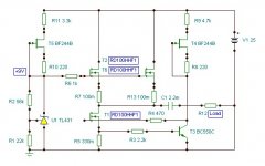
I am making tests of a "light" version of this follower, only one RD100 as VT1 and VT2, current 3A, gate bias of VT1 only 18V (two 9V batteries), rail voltage on the drain of VT1 only 48V.
Also I put Allen Bradley 1W resistors fir R1 (2k4), R2 (33k) and Silver-Mica cap for C2 (47pF). As was expected, sound has got some additional ultimate vitality, but less maximum power.
Also I put Allen Bradley 1W resistors fir R1 (2k4), R2 (33k) and Silver-Mica cap for C2 (47pF). As was expected, sound has got some additional ultimate vitality, but less maximum power.
MiiB,
you have made a number of unfortunate incorrect assumptions lately.
As stated, there´s no such thing as "single ended push pull".
you have made a number of unfortunate incorrect assumptions lately.
Improvement in what regard?Maybe a concept to take out the big capacitor driving the loudspeaker.
idea is to have two identical single ended amplifiers drive a load placed between them...then the middle potential is nulled and the need for the capacitor is no longer there...question is..will it be an improvement..??
is it then single ended push pull...???
As stated, there´s no such thing as "single ended push pull".
Also I should mention, that there is no need in source resistor (0,1Ohms) for VT1.I am making tests of a "light" version of this follower, only one RD100 as VT1 and VT2, current 3A, gate bias of VT1 only 18V (two 9V batteries), rail voltage on the drain of VT1 only 48V.
Also I put Allen Bradley 1W resistors fir R1 (2k4), R2 (33k) and Silver-Mica cap for C2 (47pF). As was expected, sound has got some additional ultimate vitality, but less maximum power.
WuYit
why do you make statements that just hangs in the air....if you disagree at least you have to explain..not just make statements...
I did not claim it to be an improvement...I just let the question hang in the air....because what is the lesser evil...the output capacitor or two single ended amplifiers working push pull..??
and the question on how to make the balanced drive....via a transformer or floating or..??? so while the amplifier seems quite simple then the balanced drive could pose a problem....
It is push pull driven by single ended amplifiers...thus single ended push pull...and it is a lot different than complimentary or quasi complimentary push pull....but off course they are all push pull in the broadest off terms.. (don't want to argue...)
Vladimir.. could you not save a little on the design by using IRF's in the current source...will the current source be more ideal with the faster device..???
michael
Hi,
I have a question, specially for Vladimir:
what makes the RD100 such a good device for this type of amplifier?
It is a HF fet, but we are dealing with AF.
Are there any specs of this fet which make it superior to the more common lateral mosfets or even depletion power mosfets which show up in comparable amp topologies lately?
Hi,
I have a question, specially for Vladimir:
what makes the RD100 such a good device for this type of amplifier?
It is a HF fet, but we are dealing with AF.
Are there any specs of this fet which make it superior to the more common lateral mosfets or even depletion power mosfets which show up in comparable amp topologies lately?
I proceed from the criterion
quality = (transconductance) / (parasitic capacitance)
As per this criterion, only other HF mosfets and tubes can compete with RD100.
It is my guess, that naturalness of sound from good tube devices has two main reasons: small parasitic capacitances + less electrolytes used
Not forget, parasitic capacitances of MOSFETs, not only relatively high, but also nonlinear.
Listening to this follower and comparing to 300B SE tube amp, I conclude that my suggestions are not wrong.
Vladimir
How does Allen Bradley Do you any good...They are in other applications dull and matte in the sound and the carbon is noisy, that is compared to types like caddok....
michael
How does Allen Bradley Do you any good...They are in other applications dull and matte in the sound and the carbon is noisy, that is compared to types like caddok....
michael
MiiB,
you don´t read my comments thoughtfully.
Balanced topologies are inferior sound wise, when sound quality has number one priority, single-ended is the obvious choice. The practical disadvantages are, however, huge. For instance, an unclean power will ruin the sound, one reason is that single-ended amplifiers amplify "everything" just as amplifiers should do. A large capacitor bank and preferably also a big choke are indispensable. If you are not prepared for that, maybe it is better to go for a balanced circuit.
In any amplifier regardless topology, the audio signal passes through all parts, thus the power supply components, it would be weird if not. Each component has to be chosen with equal care. Essentially, you listen to your power supply modulated by the amplifier circuit.
Again (for fifth time), single-ended amplifiers don`t operate in push-pull mode. They carry the whole signal waveform, making a profound difference.
- Status
- Not open for further replies.
- Home
- Amplifiers
- Solid State
- Modified Follower-99 With HF Transistors