I browsed this thread, but didn't read every post in it. If my question was answered already, please accept my apology. (A link to the reply will be appreciated).
I have a general question concerning calculating the ripple voltage in an LCRCRCRC (after the rectifier bridge). (In my case, it's for tube pre-amplifier, with a shunt regulator following the PSU filtering. However it is a general question for such filtering).
I know that Ripple V = I / (f * C), or It = CV. However, that formula applies to 1 capacitor in the filter (or few parallel capacitors, which are calculated as 1 big capacitor).
I also know that for 1/2C*R*1/2C the ripple is lower than for 1C.
Is there a formula, or another way, to calculate, or simulate, the ripple voltage for CRC filer?
Also, is there a formula, or another way, to calculate, or simulate, the ripple voltage for LC or LCRC filer?
You could do a Fourier expansion of a ripple sawtooth, run the harmonics through your filter's transfer function (the attenuation depends on the cutoff points and Q, after all), and add them back up to find the resulting waveform. Faster and less hassle to run a Spice sim though.
Given what high voltage caps and large value inductors cost I'd bet a Maida regulator such as this one would be easier, cheaper, and yield better performance.
Given what high voltage caps and large value inductors cost I'd bet a Maida regulator such as this one would be easier, cheaper, and yield better performance.
You have a way of passively filtering mains harmonics out of the supply of a class B audio bandwidth load for less than USD $1 which results in a more stable supply to the load than a regulator? Do share. 😉Use a ripple filter instead. Less costly and a lot cheaper!
…
Given what high voltage caps and large value inductors cost I'd bet a Maida regulator such as this one would be easier, cheaper, and yield better performance.
…
Thanks.
Did you try to compare the two options? What are your impressions concerning the sound quality differences?
I'm not much of a tube builder so can't really give you subjective impressions (not that they're of use anyway; people can use opposite terminology to describe exactly the same thing) but you can work out the tube's PSRR based on its biasing---it won't be much; 6dB or so---and the resulting SNR/SFDR into the next stage (or OPT) to a good approximation in Spice for both topologies. Up to you decide how many dB is satisfactory for this but 80+dBFS is probably a good starting point. You'd need to be quite a bit more specific about your build for folks to help you out with this; probably best to start a different thread with the details.Did you try to compare the two options? What are your impressions concerning the sound quality differences?
Back of the envelope, assuming full wave rectification, the passive filter would need to provide O(100dB) line rejection at 100/120Hz to be competitive with a decent HV regulator implementation. This has a way of being difficult to achieve in most passive layouts but, if one ignores layout concerns, using the highest filtering order you mention---fourth---suggests the filter would need to corner around 5Hz. You'll likely want inductors of O(1H) for that and they'll probably run somewhere around USD 25 each. That's about the same as the parts BOM for the regulator.
As something of an aside, where I ended up when I went down this path was FET tube emulation circuits off of yer bog standard LM78xx regulators. Those start around 20 cents for the devices and 65 cents for the regulators, the supplies are trivial compared to running HT and the heaters, you have more control of the added harmonics, and the sound tends to end up cleaner. They don't glow in the dark, though. Well, unless you've got something rather wrong...
I'm not much of a tube builder so can't really give you subjective impressions (not that they're of use anyway; people can use opposite terminology to describe exactly the same thing) but you can work out the tube's PSRR based on its biasing---it won't be much; 6dB or so---and the resulting SNR/SFDR into the next stage (or OPT) to a good approximation in Spice for both topologies. Up to you decide how many dB is satisfactory for this but 80+dBFS is probably a good starting point. You'd need to be quite a bit more specific about your build for folks to help you out with this; probably best to start a different thread with the details.
Back of the envelope, assuming full wave rectification, the passive filter would need to provide O(100dB) line rejection at 100/120Hz to be competitive with a decent HV regulator implementation. This has a way of being difficult to achieve in most passive layouts but, if one ignores layout concerns, using the highest filtering order you mention---fourth---suggests the filter would need to corner around 5Hz. You'll likely want inductors of O(1H) for that and they'll probably run somewhere around USD 25 each. That's about the same as the parts BOM for the regulator.
As something of an aside, where I ended up when I went down this path was FET tube emulation circuits off of yer bog standard LM78xx regulators. Those start around 20 cents for the devices and 65 cents for the regulators, the supplies are trivial compared to running HT and the heaters, you have more control of the added harmonics, and the sound tends to end up cleaner. They don't glow in the dark, though. Well, unless you've got something rather wrong...
Hi,
Thank you.
I appreciate your response.
However, by my experience I know that at times there are differences between engineering reasoning and sound quality.
Since my aim is to attain the highest possible sound quality, I don't intend to try and save some $200 or even $500 on a solution that isn't tested sound-wise.
I'd appreciate replies of how to calculate ripple voltage on CRCR filter.
I'd appreciate replies of how to calculate ripple voltage on CRCR filter.
Don't calculate it, sim it. LTSpice is your friend. If ultimate SQ is your goal then use LC, not RC filtering.
Don't calculate it, sim it. LTSpice is your friend. If ultimate SQ is your goal then use LC, not RC filtering.
Hi,
Thank you.
How do I sim a power transformer in LTSpice?
As I wrote above, it's going to be LCRCRC… filter.
The nice thing about simulation is that you can go the extra yards if you really want to, providing you're willing to do some extra fiddling, or hunt down other's efforts ... as it just happens, there was a recent conversation in the LTspice user forum at Yahoo: Yahoo! Groups, in a thread called "Simulating Frequency Dependent Inductor"
One needs to join the group first to see this material ...
Frank
One needs to join the group first to see this material ...
Frank
I don't try to sim the trafo myself, rather I use a sine source and feed that through a diode bridge. That works well enough to get the waveform into the filter looking how it looks on my scope.
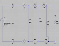
It doesn't work at all with a sine source. See the attached schematic. I get all zero voltages and currents.
Attachments
I don't try to sim the trafo myself, rather I use a sine source and feed that through a diode bridge. ..........
you don't have a rectifier bridge.It doesn't work at all with a sine source. See the attached schematic. I get all zero voltages and currents.
You have two series diodes, which are no different from a single diode.
And which solution would that be?
Fast, soft switching diode bridge, followed by a 10H common mode choke, followed by CRCR… filtering, all capacitors are Wima GTO MKP 80uF, 600V film capacitors.
Note the date on Michael Maida's app note and the relevant threads here on DIYA. If that was in reference tube and OPT emulation, most of the direct discussion and implementation is on sites other than DIYA but there's not exactly a shortage of unintentional tube emulation here---single ended class A MOSFET builds are a good place to start within DIYA.
I have no clue what you wrote here and what is your point.
However:
1. At times there are differences between the way certain circuits are simulated and measured and between the way certain circuits impact the sound quality.
2. The solution I described above is proven as for the sound quality it provides. Unless I'd have testimonies of comparisons between the solution I described above and the Maida regulator, I wouldn't use the Maida regulator without comparing it myself to the solution I described above.
3. The power transformer and the PSU case will be custom ordered by me after finalizing the schematic, prior to actually building the circuit. The 80uF, 600V film capacitors are huge (I have already 10 of them). I need to calculate how many of those capacitors I'll use, prior to ordering both the power transformer and a proper PSU case.
Shalom Joshua,
Why have you decided to use such high voltage capacitors as 600v each? That seems rather high for the power supply when you are using the capacitors in parallel. A lower value such as 150v would be much smaller if you are going to use film capacitors. Why did you feel the need to use all film capacitors rather than electrolytic capacitors if I am reading what you are doing correctly? Most people if they are using film capacitors only use them in conjunction with electrolytic's for bypass closer to the output devices and then I think they are rather small values. Are you building a vacuum tube amplifier?
Why have you decided to use such high voltage capacitors as 600v each? That seems rather high for the power supply when you are using the capacitors in parallel. A lower value such as 150v would be much smaller if you are going to use film capacitors. Why did you feel the need to use all film capacitors rather than electrolytic capacitors if I am reading what you are doing correctly? Most people if they are using film capacitors only use them in conjunction with electrolytic's for bypass closer to the output devices and then I think they are rather small values. Are you building a vacuum tube amplifier?
Nor does it matter as you've already locked on a passive filtering solution. 😉I have no clue what you wrote here and what is your point.
Shalom Joshua,
Why have you decided to use such high voltage capacitors as 600v each? That seems rather high for the power supply when you are using the capacitors in parallel. A lower value such as 150v would be much smaller if you are going to use film capacitors.
Hello and Shalom,
The output of the PSU filter will have about 325V, so I needed at least 400V capacitors. The capacitors were purchased originally for a tube Power Amp with higher HT, a project which I abandoned. Anyhow, I have already 10 capacitors of those values.
Why did you feel the need to use all film capacitors rather than electrolytic capacitors if I am reading what you are doing correctly?
I chose film capacitors because of they have a much better influence on the amp's sound quality.
Most people if they are using film capacitors only use them in conjunction with electrolytic's for bypass closer to the output devices and then I think they are rather small values.
I'm not most people. I'm an audiophile first and DIY enthusiast only in second place. My considerations are both technical/engineering and sound quality, while sound quality is my first priority. Between few viable options from the technical/engineering viewpoint, I'd choose that option which has best impact on sound quality.
Are you building a vacuum tube amplifier?
Yes, I wrote it in my first post in this thread, a day or two ago.
Nor does it matter as you've already locked on a passive filtering solution. 😉
This isn't what I wrote.
Post 1829 states a requirement for Maida adoption, specifically that testimonials be provided. It also strongly suggests links previously provided have not been looked at and options such as copy/pasting Maidia into DIYA's search box have not been pursued---this follows from the requirement for testimonies, as either of these actions would yield such within minutes, if not seconds. Further, it states the caps for passive filtering have already been acquired and indicates stating the reasons for not using a regulator is higher priority than taking a look at the option. Sounds pretty locked to me. Which is just fine; 'tis your project, it would be kind of a shame not to use a stash of caps that nice, and said caps are overkill in a regulated HV supply.
If specific objective concerns emerge based on consideration of both options those design tradeoffs would be interesting to discuss (though if cap sizing isn't the pivot it should go on another thread so as not to be off topic). Until then, I think we're done here.
If specific objective concerns emerge based on consideration of both options those design tradeoffs would be interesting to discuss (though if cap sizing isn't the pivot it should go on another thread so as not to be off topic). Until then, I think we're done here.
It doesn't work at all with a sine source. See the attached schematic. I get all zero voltages and currents.
What Andrew said. Plus looks like you only have an operating point sim set up (the .op visible on your schematic), whereas you need to run a transient analysis.
Post 1829 states a requirement for Maida adoption, specifically that testimonials be provided.
Yet testimonials wer not provided.
It also strongly suggests links previously provided have not been looked at and options such as copy/pasting Maidia into DIYA's search box have not been pursued---this follows from the requirement for testimonies, as either of these actions would yield such within minutes, if not seconds.
I did a search and found no testimony concerning the differences in sound quality between well filtered (discreet, like CRCR, or LCRCR) PSU and the Maida regulator.
I found only one testimony saying that the Salas Simplistic Mosfet HV Shunt regulator is superior to the Maida, concerning sound quality. It was my initial intention to use the Salas Shunt Regulator, however it requires not much more than 5V ripple, hence, I need to provide the required filtering, prior to the regulator.
Further, it states the caps for passive filtering have already been acquired and indicates stating the reasons for not using a regulator is higher priority than taking a look at the option. Sounds pretty locked to me. Which is just fine; 'tis your project, it would be kind of a shame not to use a stash of caps that nice, and said caps are overkill in a regulated HV supply.
I do have 10 such capacitors, but I wouldn't use all of them. I'm looking for the minimum number of capacitors that will provide enough filtering. I'd go for only one or two capacitors with Maida regulator, should there be testimonials concerning the difference in sound quality between all passive filtering versus the Maida regulator. I encountered only one testimony that the Maida sounded better, compared to passive filtering which was insufficient, that is, the passive filtering had too high ripple voltage. Such a comparison is meaningless. A meaningful comparison will be between a passive filter with adequate filtering and the Maida.
If specific objective concerns emerge based on consideration of both options those design tradeoffs would be interesting to discuss (though if cap sizing isn't the pivot it should go on another thread so as not to be off topic). Until then, I think we're done here.
Again, cap size do matter to me, with or without Maida. I'm trying to figure out the minimum number of capacitors that will give me no more than about 5V ripple, to consumption of 190mA.
Since you suggested the Maida in order to reduce capacitors capacitance, discussion of the difference in sound quality between the two option is right on topic.
Should you are being repelled by all and any discussion concerning sound quality, such a discussion is of topic for you, not necessarily for all.
What Andrew said. Plus looks like you only have an operating point sim set up (the .op visible on your schematic), whereas you need to run a transient analysis.
If you'd look at schematic, I used only 2 diodes, like what Andrew said. I also have the .op visible in the schematic. Still I get all zero voltages and currents.
I have looked at the schematic, seems you have not digested what I'm saying about needing to run a transient analysis, not an operating point. Right click on the text '.op' which opens the window where you select the kind of sim, the left most tab is what you want. Fill in details like how long you want it to run and how precise you want the results (min timestep). Bear in mind that a diode feeding an inductor directly will give simulation problems when the diode switches off as the inductor current has nowhere to go....
- Status
- Not open for further replies.
- Home
- Amplifiers
- Power Supplies
- Modelling an L C R power supply