The simulated ripple voltage should be about as accurate as your modeling and simulation. If you draw the current in the same way the load will, then the ripple will be closer to accurate. You also should usually model the reservoir capacitor parasitics, such as ESR and ESL
If the load will be an active circuit, then you might want to also simulate that, to see what the ripple will do, unless all you care about is an average. Sometimes current sources can be used to construct pretty-good simulated active loads.
If you are worried about the frequency and temperature dependence of any electrolytic caps' ESR, etc, the Cornell Dubilier website has a Java applet that will produce frequency-dependent Spice models for (their) electrolytics that will run in transient (time-domain) simulations.
Sometimes you also need to model the parasitic inductance and resistance of the conductors.
Last edited:
Hi,
Thank you.
I use only film capacitors, not electrolytic.
I don't have the manufacturer's ESR and ESL data, so I dialed in estimated ESR values (0.01 Ohm), no ESL.
Fiddling with the values of the chokes and the capacitors, the results do make sense.
Thank you.
I use only film capacitors, not electrolytic.
I don't have the manufacturer's ESR and ESL data, so I dialed in estimated ESR values (0.01 Ohm), no ESL.
Fiddling with the values of the chokes and the capacitors, the results do make sense.
PSUD2 allows either C, or LC (one L and one C), or RC (one R and one C). It cannot have LCRC. Also the ripple voltage shown by PSUD doesn't make sense, it isn't correct.
An externally hosted image should be here but it was not working when we last tested it.
Last edited:
PSUD2 allows either C, or LC (one L and one C), or RC (one R and one C). It cannot have LCRC. Also the ripple voltage shown by PSUD doesn't make sense, it isn't correct.
No it doesn't, I think you are using it incorrectly. Here is a link to an article where, amongst other things, the writer shows 2 LC cells and an RC added on the PSUD screen.
http://www.dhtrob.com/overige/pdf/dhtrob_psu.pdf
I haven't used the program for a while but I found it to be excellent.
Okay, I managed to have LCRCRC in PSUD2, however the ripple voltage results don't make sense, they cannot be correct. For instance, L=20H(36R)+C1=80u(0.1R) I get less than 1V ripple. Adding R1=6R6+C2=80u(0.1R) I get again less than 1V ripple. However, changing C2 to 1u(0.1R) I get ripple of about 10V. This cannot be correct.
P.S.,
No matter how many RCRCRC limbs I have, when C=80u, the minute the last C is 1u, the ripple voltage rises to over 10V.
No matter how many RCRCRC limbs I have, when C=80u, the minute the last C is 1u, the ripple voltage rises to over 10V.
Joshua I will need to go in and try to replicate this myself when I get the time. However, what I have to ask is, is that 20H 36R choke a real part? If so it must be huge!
P.S.,
No matter how many RCRCRC limbs I have, when C=80u, the minute the last C is 1u, the ripple voltage rises to over 10V.
I think you have a supply resonance. Try playing with (raising) the R value in your RC filter.
Joshua I will need to go in and try to replicate this myself when I get the time. However, what I have to ask is, is that 20H 36R choke a real part? If so it must be huge!
Hi Robert,
Thank you.
Indeed, that choke is a real part, a Lundhal one. Actually I made a mistake, it's a 10H choke. I corrected the choke value in PSUD2, however the high ripple for 1uF capacitor doesn’t change – wherever the 1u capacitors is placed is placed in the RCRCRC chain. This is weird, it doesn't make sense to me.
There is even weirder phenomenon.
I simulate for actual tube preamp I'm going to build. I have already more than enough number of 80U 600V film capacitors. The choke is to be ordered. The PSU is going to be in a separate enclosure. I thought of having an RC filer of 2x3.3R (one for (+) and one for (-) wire) and 1u in the preamp enclosure. In the light of PSUD results, I changed the last capacitor (which will be in the preamp enclosure, but is included in PSUD simulation) to a 4u one. When the capacitor one before last in PSUD (last in the PSU enclosure) is 1u I get better ripple on the load than when it's 2u. I'm not sure if I can rely on PSUD when it comes to ripple voltage.
Hi Robert,
Thank you.
Possibly it's supply resonance. Increasing the resistors in the RC chain from 6.6R (2x3.3R) to 9.4R (2x4.7R) makes no difference. It looks like the smallest capacitor I can put anywhere in the RCRCRC chain is 4u. With resistors value of 24R the smallest capacitor I can have is 2u. Since with few 24R resistors I loose too much voltage, I resorted to 9.4R resistors in the chain, with the last 2 capacitors 4u each. Still I wonder how reliable PSUD is.
Also I wonder if indeed 10H choke plus 168uF (altogether) really gives less than 1V ripple. Even 10H plus 98uf gives (according to PSUD) a little over 1V ripple.
PSUD2 does sometimes produce strange results. There was a thread on here a few weeks ago which reported problems when 'snubbers' were added (modelled by having an unusually large ESR for one of the caps).
It ought to be possible to estimate the ripple behaviour of a power supply using paper and a calculator.
It ought to be possible to estimate the ripple behaviour of a power supply using paper and a calculator.
Hi,
Thank you.
Indeed, ripple can be calculated easily for a given capacitance, but I don't know how to calculate ripple for LC filter and for RCRCRC filter.
Possibly and regrettably there is no way to accurately simulate ripple in such filters (LCRCRCRC).
Thank you.
Indeed, ripple can be calculated easily for a given capacitance, but I don't know how to calculate ripple for LC filter and for RCRCRC filter.
Possibly and regrettably there is no way to accurately simulate ripple in such filters (LCRCRCRC).
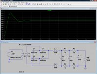
1.1Volt in 319Volts is very good! If there is a problem, send some of the ripple to the grid bias at 180 out of phase.
- Status
- Not open for further replies.
- Home
- Amplifiers
- Power Supplies
- Modelling an L C R power supply