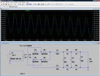
Joshua, try this LTSpice sim.
Ripple is far from 1V.
Hi,
This simulation doesn't make sense, there is something wrong: for 380Vac in it shows about 230Vdc.
380V peak.
380Vpk = 268vrms.
Choke input supply, Vout = 0.9 Vin(rms) = 241 VDC
Vout at load = ~220v. Therefore current = 0.1A. Loss in 10R resistor = 1v, loss in 36 ohm choke 3.6v. 2 chokes + 4 resistors, total loss 11.2v. 241-11 = 220v.
380Vpk = 268vrms.
Choke input supply, Vout = 0.9 Vin(rms) = 241 VDC
Vout at load = ~220v. Therefore current = 0.1A. Loss in 10R resistor = 1v, loss in 36 ohm choke 3.6v. 2 chokes + 4 resistors, total loss 11.2v. 241-11 = 220v.
Okay, thank you.
With 10H (2x5H, which is the actual choke) and combined capacitance of 82u, I get ripple of about 2V. Is it possible? Is it a realistic result?
With 10H (2x5H, which is the actual choke) and combined capacitance of 82u, I get ripple of about 2V. Is it possible? Is it a realistic result?
What is your load? It's not unrealistic, depends on the exact configuration.
The load is 190mA (about 1.8K on about 340Vdc).
You can see what I get here. The choke input filter needs ~535V pk (~380vrms), the cap input filter needs 340V pk (~240vrms). Transformer voltages are rms.
These values are realistic. These are typical tube PSU configurations. When you look at a few circuits you will see values like these, some are higher specified for preamps, some lower for power amps and depending on type of amp and PSRR. If you are building a prototype build it point-to-point with plenty of room in the chassis so that you can modify it a bit if you end up with too much hum. You can increase the caps or add another RC stage, it will cost you a few B+ volts, but this is unlikely to be critical.
An externally hosted image should be here but it was not working when we last tested it.
These values are realistic. These are typical tube PSU configurations. When you look at a few circuits you will see values like these, some are higher specified for preamps, some lower for power amps and depending on type of amp and PSRR. If you are building a prototype build it point-to-point with plenty of room in the chassis so that you can modify it a bit if you end up with too much hum. You can increase the caps or add another RC stage, it will cost you a few B+ volts, but this is unlikely to be critical.
Okay, thank you.
With 10H (2x5H, which is the actual choke) and combined capacitance of 82u, I get ripple of about 2V. Is it possible? Is it a realistic result?
Attachments
Use the AC version of Ohm's Law. An LC filter is just a potential divider.Joshua_G said:Indeed, ripple can be calculated easily for a given capacitance, but I don't know how to calculate ripple for LC filter and for RCRCRC filter.
You can see what I get here.
…
These values are realistic.
…
Thank you.
The values in your schematic are unrealistic, so I wonder…
euro21,
Thank you.
It looks excellent on the simulation.
I wonder if anyone verified the simulation results of such a PSU (LCRCRC) with actual measurements.
Use the AC version of Ohm's Law. An LC filter is just a potential divider.
Thank you, I will.
Thank you.
The values in your schematic are unrealistic, so I wonder…
What are you talking about? 10Henries, 40+40uF. 6R6. 320V, 190mA. That's what you said. Plus extra 80 uF in the cap input example...
Last edited:
What are you talking about? 10Henries, 40+40uF. 6R6. 320V, 190mA. That's what you said. Plus extra 80 uF in the cap input example...
Oops, my mistake, sorry. You wrote the values in Farad units.
- Status
- Not open for further replies.
- Home
- Amplifiers
- Power Supplies
- Modelling an L C R power supply