Do you think you have the phase of the NFB correct. With the NFB disconnected the NFB from the speaker output and the input signal should be in phase. It may be opposite from the original design. It may be necessary to swap the KT88 plates and screens over to the opposite ends of the OPT. From memory there is a connector there on the OPT which you can reverse all 4 signals.
Last edited:
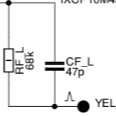
I was wondering about that.... Would the easiest way to find out is just to reverse the OPT primary leads (orange/black & violet/black), or is there an easier way? Another question....... Reversing the outputs of the phase splitters does not reverse the phase at the OPT secondaries, does it? Also, the "original" easychip mod used a 47pF cap in the feedback loop but you chose to use a 10pF. I was wondering why (?). Thanks.
If you reverse the OPT wires don't forget to do the UL screens too. As Kay says that will also reverse the phase of the LPT plate connections if its easier. The NFB components I don't have a model of the OPT so cannot work these out. It may be a case of trial and error. First check you have negative not positive feedback.
So, I would need to change all 6 primary wires around for each OPT? Swap brown with green, black with orange, and other black with violet?

So am I! To do NFB you really do have to have a bit of math understanding. Otherwise it turns into a black art. Without a model of the OPT I cannot give you component values. The other options is for you to take a Bode plot (amplitude and phase) and we can try and fit the model to the data.
After getting the feedback phase correct I might experiment with the value of the feedback cap by using a variable 3pF-50pF, a square wave input and my scope, adjusting it for the best linearity. Would this be a good or bad idea?
Never heard of a Bode plot, must Google.......
Never heard of a Bode plot, must Google.......
Yep. From memory the transformer is not that good at HF. So that means placing the dominant pole quite low (say 8KHz). The cap your talking about is the lead compensation. There is a good article on this just cannot find it.
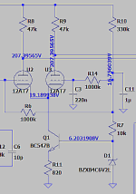
In the plate ckt. of the 12AX7 there is C5 and R13. This is an RC filter of some sort, isn't it? What is it's purpose?
Yep. C5 and R4 in parallel with 12AX7 Ra are the dominant pole which you would set to 7-12KHz. C5 and R13 are the zero which would be say 50KHz and matches the first pole of the OPT. C6 and R12 should also be at about 50KHz. There's no simple way to explain - you are building a lead-lag compensation network.
I'm sure you be correct, Kay! After reading most of the amp compensation html from the link above I'm very much convinced that feedback is much more complex and intimidating then I thought. :-(
Sorry this does not include the grid stopper on U3 and I am not sure which CCS you ended up using.
I have added some real parameters to the ZD043 OPT model based on sketchy info elsewhere (-3dB BW 3-125KHz). I find the circuit very close to instability at about 2Hz. If you back to the original K4040 schematic C8, C7, C10, C9 (referenced on #97) are 22nF - that's why. This makes it much more stable. However thats a break frequency of ~30Hz which is too high and could result in the driver stage clipping. I have made them 47n, but made the NFB more complicated with the addition of C12 R33. This is lead compensation similar to what C6 does at HF, but at LF. C12 can be a electrolytic +ve up bypassed with a metal film or just a metal film - it only has 1V across it. You could also go back to the simple NFB with the 47nF for C8... but increase C4 to 1-2uF but at 400V its big. Even then its not as stable. As usual nothing is simple with NFB...
Interesting the HF looks OK but again its just a guess.
Last edited:
Hummmmm........must order mo' parts it seems. I do not have the 47nF caps. I didn't end up installing the grid stopper resistor. Do you think that I need it? I ended up using the BC547B based current mirror that you posted. As far as I could tell it worked good, as did the 10M90S's. Thanks again for your hard work in trying to help me make the most of this project.


Well, I got my parts and made the NFB to match the schematic with the addition of C12 R33. I also changed C8, C7, C10, C9 to 47nF and had to reverse the output transformer phase. However, the gain was super low so I tried a 47pF across a 68K resistor and and gain was good and it sounds fantastic. I think I may put the covers on it and listen to it for a while. I've spent more time tinkering with it and now I just want to listen to it and enjoy. ....plus there are other summer projects that need my time.
 Thanks again to everyone who has had the patience to help me, especially baudouin0 and Kay.
 Thanks again to everyone who has had the patience to help me, especially baudouin0 and Kay.
- Home
- Amplifiers
- Tubes / Valves
- Modding a Velleman K4040