So your at 415V at 50ma which is 21W. So you are within the 35W so you can use 220K. However you also need to include the bias pot resistance of 100k which could be up to 50k with the 100k to ground. I think you would be OK with 150k as the grid leak resistor. As for the bias maybe -55V is needed so you need at least -60V on the pots.
Do you think that by changing R5 & R10 to 10k would give me close to the -60V on the pots?
I ordered some 100k Bourns pots to replace the stock ones as a possible safety measure.
I ordered some 100k Bourns pots to replace the stock ones as a possible safety measure.
Maybe, maybe nearer 4k7. Note you will need a bigger cap after the 4k7 and pots to remove the ripple. C30 220uF C31,C29 100uF
Thanks, I'll make those changes. Must order mo' parts.....🙂
Another question..... Since I will have a DC heater supply for V11, there wouldn't be any advantage to doing the same for V9, would there be?
Another question..... Since I will have a DC heater supply for V11, there wouldn't be any advantage to doing the same for V9, would there be?
I will simulate the complete mod yes. As for the OPT the ZD043 I don't have data on and the model is for a perfect transformer. I do have a model for ZD043 but do for the amplimo 100PP2K2S. This will give a rough check on the NFB. You will need to do a square wave test however. Understand its not my change to a LPT.
Thanks a lot for all your help! Much, much appreciated..... I have a function gen & scope so I can check for ringing when driven by a samll amplitude square wave. alexcp told me that he found that he only needed the CC_l 22pF cap across R59 for the L ch. because that channel Is connected to the input triode via long PCB traces.
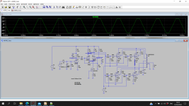
Just started simulation. There's a problem with DC stability in the second stage. Depletion mode current sources have quite a spread of the current they generate dependent on device. However the grid voltage of the 12AT7's are derived from the cathode. This results in a big spread of cathode voltage from near zero to over 200V with only small changes in current. This configuration is intended to be used with a tail resistor rather than a CCS. Fortunately there's a simple solution. This is to set the grid voltages to just a fixed value using a potential divider.
Attachments
Kay, the problem is that they have used 1M from the cathodes back to the grids which gives a very big variation of cathode voltage with CCS current. I've just set the grids to say fixed 10V bias. Its not brain surgery. The self bias approach only works if you have a tail resistor not CCS. I don't like using mosfet or BJT's for CCS. Its OK for prototyping but not in production as you get a big spread of currents they generate from one device to the next.
Attachments
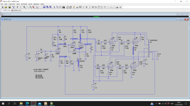
Well that works for me. The NFB components will need adjusting for the OPT. Its slightly different from the mods published in that the grids of the second stage are biased to a fixed voltage which is not critical. The tail resistor on the CCS may need adjusting to get about 6.5ma through the CCS. Think that will work quite well.
Attachments
I hesistate to ask a dumb question, can R11 be a variable resistor to adjust for 6.5ma to be measured by a ma meter inserted between M1 and cathodes? Or....?
I think just a fixed resistor but you can always try it with your 10M45 on a breadboard or something before fitting. Your just OK with drive to the KT88's so I would keep grid leaks at 150k. Otherwise the anode resistors may have to be 33k and the current higher - I think your OK with 12AT7 plate dissipation but not checked.
I will accumulate parts and mod according to the schematic that you posted......unless you run into something that needs changed. How will I know if the 12AT7 plate dissipation is acceptable? No way of knowing how close the NFB will be to OPT with published values, correct?
Thanks a lot for your work in simulating this mod.. It will take some time to accumulate parts and I need to sell a couple of things on Ebay to finance the KT88 purchase but I am excited to pursue this project and hopefully end up with a better sounding K4040.
Thanks a lot for your work in simulating this mod.. It will take some time to accumulate parts and I need to sell a couple of things on Ebay to finance the KT88 purchase but I am excited to pursue this project and hopefully end up with a better sounding K4040.
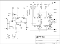
C2 is electrolytic on original K4040. C3 is low voltage so metal film. There are some voltages on the simulation.
The design as is features a negative voltage for fixed bias. I'd return the CCS to this negative bus and the grid via leaks to ground. This will result in stable conditions....the problem is that they have used 1M from the cathodes back to the grids which gives a very big variation of cathode voltage with CCS current.
Best regards!
- Home
- Amplifiers
- Tubes / Valves
- Modding a Velleman K4040