Maybe even leave the MOSFET's gate at ground (via a small safety resistor) and take the source from the negative voltage through a (much larger) resistor. This would swamp the variations of various MOSFETs and better define CCS current, thus anode voltages. Maybe leave grids as-is for higher common mode headroom in the CCS. Lotsa possibilities.
All good fortune,
Chris
All good fortune,
Chris
Yes, possible with a FET CCS. I was thinking of a - maybe even cascoded - BJT one.
Best regards!
Best regards!

IN7050 is a zener so is not a CCS.
CCS to negative rail, grids at ground or CCS to ground grids at +10-15V swings and roundabouts. CCS to negative rail will dissipate .4W. It will also cause the negative rail top drop a bit when your already a bit short on volts. So me safer to take CCS to ground and you don't need more wires to bring in the negative rail.
Lots of ways of doing CCS. FET's and MOSFET big spread of current over different devices. No problem for prototyping. I think diy audio like them as they are a bit like valve. I don't. Best to have a resistor in the drain else there is no way of setting current. I tend to use a zener diode and a NPN. A current mirror is another option, some take a resistor split from the two LPT plates and have an unequal current mirror. This has some DC negative feedback. There's also some 3pin chips which you can use as CCS such as the LM334. Current is predictable and compliance voltage (the min voltage over which the current is constant) is very low. You can even use a pentode if you have enough voltage. All will work. Unless they are terrible will make very little difference to the audio. Even a simple resistor to the negative rail will work sort of.
The only thing not to use is the published mod. The grids do need to have a fixed voltage on them. I am just simulating to your brief checking that there are no pitfalls I can see. If you want to use a MOSFET or JFET do so. Make sure it will give at least say 10ma min when Vgs = 0V.
Last edited:
I'm really not that much of an expert, especially if it comes to SS, but what I understand is that a CCS needs an as high as possible impedance the cathodes look into and as low as possible parasitic capacitance. A BJT CCS's impedance is high when the transistor's hFE is high, as is the emitter resistor. But what's best in these terms? Is a FET superior to a BJT? Is a LM334 better than both?
My standard CCS design is a cascode, with a BC550C as the lower transistor and an upper one that needs to be chosen wrt. to the total voltage drop, preferably a video transistor, due to it's low collector capacitance. For low tempco, the lower zener should be in the range of 6.2 V, connected in series with a plain 1N4148 (or the BE junction of another BJT) that needs to be bonded thermally to the lower CCS transistor. The upper tranny's base voltage needs to be set in order that the lower BJT's dissipation and voltage ratings won't be exceeded. I'm referring here to what Morgan Jones said in his Valve Amplifiers, 3rd edition.
Best regards!
Interesting question you ask how good does it need to be. Well the higher the impedance the better the LPT balance. Given the output stage balance of Gm of the KT88's (matched) , I would have through maybe <2% imbalance is OK. So that will give you a minimum CCS impedance. Something you can simulate on LT spice and calculate from equations. I have found that a single high hfe NPN with zener is good enough, again simulation will show. The impedance on the cathodes will be quite low so I would think capacitance is not a problem certainly a BC550C or BC547/8 C would be fine.
The LM334 is interesting, with such low compliance voltage it may be possible to run the grids at 0V, I know Mr Summer did this I thin he used E88CC's. 6.5ma is getting a bit close to the upper range of the LM334. The higher the grid voltage the less variation of CCS current there will be for any given CCS.
The LM334 is interesting, with such low compliance voltage it may be possible to run the grids at 0V, I know Mr Summer did this I thin he used E88CC's. 6.5ma is getting a bit close to the upper range of the LM334. The higher the grid voltage the less variation of CCS current there will be for any given CCS.
Last edited:
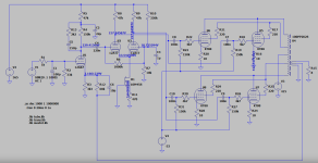
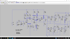
R2 could safely be made much larger, maybe up to 1M Ohm, for lighter loading of the previous stage. R11 could begin as 1K trimpot, adjust for correct anode voltages, measure the trimpot and replace it with a fixed resistor mounted very close to M1.
All good fortune,
Chris
All good fortune,
Chris
I think R2 was the same as the original. Looking at the circuit again the change I would make is to supply both grids through 1M. Without this its just possible the very small grid currents would introduce an offset. In any case both halves of the valve won't be the same and you will end up with some plate voltage offset anyway. C4 needs to be 400V but C3 can be low voltage.
Attachments
Well...........I'm still waiting on a few parts, filter caps, bias trim pots & coupling cap's but have made quite a bit of progress removing unneeded stuff and installing new components. I have all new tubes and have raised the tube sockets instead of enlarging the holes in the stainless steel plate. It may be a couple more weeks or so waiting on the stuff from China. :-( So far, so good.......I think.
Attachments

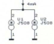
In the way of an update, I finally received all the needed parts and have installed them and started to test things. I thought I'd power it up and test the power supplies, preamp and phase splitters first and install the KT88's if everything else looked good. The first thing that I found was that the CSS 10M45S's would not conduct (plate voltage @ V2 potential). I replaced R11 with a 1K pot and same result, adjusting it from one extreme to the other, no conduction. I bought 5 of the 10M45S's from Ebay (China) and notice now that the post said "refurbished" and may not work in all applications. They are evidently defective but looked new. I had four J508's laying around so I tried 3 in parallel which gave me 200V plate voltage with V2 adjusted to 360V, not quite the 6.5ma that I need. I tried 4 but more than I needed. I also had to replace the V2's series resistor, R82, with a 10K (original 15K) in order to get 360V. Since I can't find a local source of 10M45S's and don't want to wait another month by ordering from England or China I have ordered a pair of 10M90S's from Digi-Key. They should work, shouldn't they? Anyway plate voltage is 228V for the 12AX7 preamp tube so that looks good. My V4 bias supply is -67V but the V3 plate supply measures 440V with my house line voltage at 125V. If I run my variac down to 120VAC the supply reads 416V. Is this something to worry about? The filter caps are only rated @ 450V after all. Also, the DC filament supply for the 12AX7 preamp bube works good.
Last edited:
Perhaps you'd better return those 10M45S CCS's to the negative bias supply voltage instead of ground.
Best regards!
Best regards!
I'm sorry but I don't understand.... Why would the J508's work connected between ground and cathodes but not the 10M45S's? Do you mean the negative bias supply V4 (-67V)? If so would the 1K pot still give enough range to adjust for 6.5ma? Thanks and please forgive my ignorance.
'Cause I suspect the 12AT7 cathode voltage might not leave enough headroom for the 1OM45S's to work properly. Before connecting them to -67 V, please check the device's voltage ratings that I don't know.
Best regards!
Best regards!
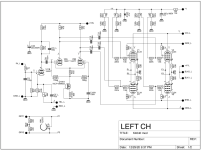
Don't you get the difference? In the 2nd circuitry the 12AT7 triodes are biased by the voltage drop across the common 470 Ω cathode resistor. The 1st schematics doesn't show a resistor like this one. So the voltage drop across the CCS is the bias voltage.
Best regards!
Best regards!
Sorry for not understanding. I was under the impression that the 12AT7's were being biased by the voltage divider R10 & R7 through R14 & R6 but don't understand how the cathode voltage is being generated I guess. Thanks for your patience in helping me.
Last edited:
Oh yes, I missed that voltage divider and the 330k to the positive voltage 😵 . Then most probably your 10M45S's are faultiy.
Best regards!
Best regards!
- Home
- Amplifiers
- Tubes / Valves
- Modding a Velleman K4040