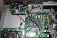
Just a follow-up to Ross' post about the mod board. The board is very well designed making it easy to solder, even if your not a pro, and I am not. I found a few good videos on the internet about soldering surface mount compoments and no problems, except for a trace from the top of the clock to the foot. Caused a few hours of frustration, but completely my fault.
A little bit harder was connecting the board to the oppo. I used very thin wire for the signals, 30 AWG wrapping wire, and 22 AWG solid for reset,ground and 3.3V. I connected the heavier wire through the bottom of the mod board ( for support) and the thin wire came in from the top. Make sure you give yourslef enough wire or you might not have enough room between the big caps on the oppo and the mode board. For the 5 V power and ground, I used the connect as per ross instructions. I lifted the white plastic connector housing from the pins on the oppo board. It just slid right up using the blade of a screw driver. I tightly wrapped 1 turn of 22 AWG to the bottom of the exposed pin, crimped and soldered. I then slid the shroud back down over the pins. Make sure the wires are pointing away from the board when you solder, that way they can fit in a little nich on the bottom of the housing. Worked great. Also do not try any wire thicker than 22 awg or you probably will not be able to slide the connector housing down far enough
Some other tips that worked for me
1) make sure the leads going through the board from top to bottom do not stick out too far, and short on the tops of the caps from the oppo. Leave some room or put something to insulate the two boards
2) I used a 3/4" spacer between the corner of the mod board and the corner of the oppo board for support on one end and the 22 awg wire for the leads mentioned above for the other end of the board
3) Get good magnification, and double check all of the solders on the board. I used a binocular microscope....
4) I recommend powering the board up with 5V and checking all of the regulators, before you mount the mod board in the oppo.
5) Be very careful with the ribbon cable that vertically connects to the oppo board. The black piece that holds it in place is pretty fragile.
6) The glue that they put on the connectors of the oppo board is a pain to remove, but if you don't you could bugger up one of the connectors.
How does it sound? Great!! More detailed than before. I think the sound from the oppo actually sounds better also.
Nice work Ross.
JimS
Hello Rossl and everyone else on this thread!
Just came back to my Tokyo home after a trip to Spain (attended a friend's wedding) and Switzerland (where I met another friend), and to my pleasant surprise the 5 x PCB from Rossl were waiting together with a complete set of instructions.
Several of our group members are very busy professionally in their day-jobs, so it will most probably take us some time to get through the building and testing.
In the meantime one of our members bought and installed the following replacement clock into his OPPO DV-981HD http://www.bursonaudio.com/Burson_Clock.htm and he also did some updates to power supply caps etc. Another DV-981HD has been kept "stock" for comparison purposes. The OPPO is used alternatively for direct output (of SACD and DVD-AUDIO) or via Assemblage Dac 2.7 & Assemblage D2D upsampler.
The Burson clock and power supply update has already been confirmed to provide a solid improvement to the OPPO (better precision, more weight etc.), so the next step will be to build and install the MOD decribed in THIS thread into the unmodified DV-981 HD and compare the two (also against other unmodified DV-981HD units that other group members have availlable).
Cheers! 🙂
Attachments
Hi I'm new to the thread.
Is the upshot of Rossl's mod to provide 96K PCM output via AES from an OPPO for an external DAC to process DVD-A and SACD signals?
From reading the thread, it also appears that disc's with a sampling rate beyond 96khz will not work, or are they just down sampled to 96Khz?
Thank you!
-David
Is the upshot of Rossl's mod to provide 96K PCM output via AES from an OPPO for an external DAC to process DVD-A and SACD signals?
From reading the thread, it also appears that disc's with a sampling rate beyond 96khz will not work, or are they just down sampled to 96Khz?
Thank you!
-David
dw8083 said:Hi I'm new to the thread.
Is the upshot of Rossl's mod to provide 96K PCM output via AES from an OPPO for an external DAC to process DVD-A and SACD signals?
Yes. You can adapt it for AES, Coax or optical.
dw8083 said:
From reading the thread, it also appears that disc's with a sampling rate beyond 96khz will not work, or are they just down sampled to 96Khz?
Thank you!
-David
The earlier version did not work with 192K DVD-Audio. The latest version resamples everything to either 96K or 192K by selecting a jumper on the board. All data rates are resampled with a low jitter clock. I have tested CD, DVD, SACD, and several DVD-Audio sampling rates.
I have two more. 😀
My email is in post 78
http://www.diyaudio.com/forums/showthread.php?postid=1165801#post1165801
My email is in post 78
http://www.diyaudio.com/forums/showthread.php?postid=1165801#post1165801
NOTICE !
All the boards have been sold.
If anyone else wants one we will wait until there is enough interest in another group purchase.
Thanks
All the boards have been sold.
If anyone else wants one we will wait until there is enough interest in another group purchase.
Thanks
I want one of the boards - kicking myself for missing out on this - hope there is enough interest to do a group purchase!
Vic
Vic
Hi Vic (altclick)
I may possibly be able to help you out with one board since our group bought 5 of them and we consider one to be a spare. Drop me a line at shellina - at - mac - dot - com
Stig
I may possibly be able to help you out with one board since our group bought 5 of them and we consider one to be a spare. Drop me a line at shellina - at - mac - dot - com
Stig
sugarn said:Please tell me where I can get the schematic of OPPO DV-981HD.
I have never seen a schematic of an Oppo. If you search the internet you can find schematics of other DVD players based on the MediaTek MT1389 chipset. This will give you a very good reference because MT1389 DVD players are all very much alike in their basic configurations. 😀
any other impressions of the mod board?
I have been listening to the oppo 98,1 with rossl's mod board, for a couple of weeks now, and I think it has really improved the sound of my best cds, SACDs and DVD-Audios. The only problem is that the poorly recordered or remasterd discs sound much worse to me, as I can hear all of the problems more clearly. There is one other problem that I can't seem to solve and that is that my auzentech x-meridian PC card does not seem to want to sync with the SPDIF or Toslink signal from the mod board, although my other DACs do not have any problems. I have written to the company and no response yet
I would be interested in hearing from other builders of the mod board...
Jims
Hi jims,
That is odd because it should work. I don't have an Auzentech.
I have tested the output of two different mod boards into an Audigy2 at 96K. If the Soundblaster Audigy drivers are used they resample the input data, but the Audigy card doesn't resample or adjust volume if I use the free kX drivers.
The kX drivers work but there is one very weird bug. SPDIF direct input doesn't always work right away. I usually get sound right away, but it can take anywhere from 10 seconds to 20 minutes before other applications can see the data. very strange
This only applies to soundcards that use the 10k2 chip. Since the Auzentech doesn't, I don't know what is wrong but it might be a similar problem.
an explanation from the kX web:
http://kxproject.lugosoft.com/direct.php?language=env
snip from web page:
...Also note that it might require up to 10 seconds for the SPDIF Input to synchronize to the incoming signal, if its sampling rate is more than 48000...
Hi Rossl
I have not had a response yet from Auzentech. When I use the oppo mod boards SPDIF or toslink input into the X-merdian card, I can hear the music from a DVD or CD, but it sounds "slow" with alot of static and distortion. If I switch to the unmodified SPDIF signal from the oppo, it sounds fine. If I input SPDIF, toslink or even AES (with the proper converters) from the mod board to my monica2 DAC it sounds great. I have tried all of the input options in the auzentech software and I still can't get it to sync. Just to make sure it was not something wrong with my board, I built a second mod board and the same thing. I think I will try another computer with a Creative card.
Any ideas?
JimS
Which SPDIF flag would cause a problem with a soundcard but not a DAC?
The VALID bit is controlled by the CS8421 chip. If the ASRC loses lock and can't resample correctly it flags the data as not valid. Normally this would only happen momentarily when changing to a disc that has a different sample rate from the previous disc that was played. It should not lose lock in the middle of playing a disc.
jims, are you sure that R13 is a 47K and is soldered in correctly? If R13 was wrong the valid bit may not be set correctly.
If pin 17 of the CS8406 transmitter were shorted to 3.3V, the VALID flag would be incorrect and always flagging the data as bad. A DAC may ignore the flag but a soundcard may honor it. Or vice-versa.
On a previous board version I had jumpers that allowed me to manipulate the COPY and ORIG flags. All my receiving devices that I tried just ignored those two bits, so on the latest version I connected pins 1 and 28 of the CS8406 transmitter to logic level 1. (3.3V). That should allow any receiver to work.
If you really want to experiment on one of your boards, pull up CS8406 pins 1 and 28 from the PCB and connect them to ground. Make sure you are not somehow shorting 3.3V to ground! Grounding those CS8406 pins 1 and 28 will put the transmitter in "consumer" mode. I'm not sure why the Auzentech would need that, but it is something to try.
The transmitter's USER bit is connected to ground. I'm not aware of a reason the soundcard or a DAC would expect data on the USER bit.
The transmitter's Emphasis bit is connected to 3.3V. The Oppo will decode emphasis on any disc that has it and the ASRC chip will always see data without emphasis.
rossl said:Which SPDIF flag would cause a problem with a soundcard but not a DAC?
The Pro/Consumer, the SCMS and the sample rate flags.
- Status
- Not open for further replies.
- Home
- Source & Line
- Digital Source
- Mod for DVD player Hi-Rez stereo PCM output - SACD DVD-A HDCD