Hi Coffin,
thank you for regulator PCBs.
I am using it for Hiraga Monstre amplifier and it works great.
4 positive regulators are set for 800mA.
I didnt compare directly by i think opamp OPA627 works better than OP27 here.
regards, Bostjan
thank you for regulator PCBs.
I am using it for Hiraga Monstre amplifier and it works great.
4 positive regulators are set for 800mA.
I didnt compare directly by i think opamp OPA627 works better than OP27 here.
regards, Bostjan
Hi
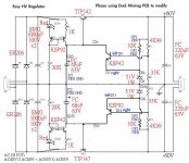
There's a cheap way to use Minireg on +-60V!
please check the schema below.
cheers
Coffin
There's a cheap way to use Minireg on +-60V!
please check the schema below.
An externally hosted image should be here but it was not working when we last tested it.
cheers
Coffin
Attachments
Got mine running today. Used BF244a instead of 2sk170 and 2n3904/3906 instead of MPSA92/42. Also used 1000uF BGs for input caps as the current drain in this case is very low (<50mA). Set it up for +/-15 rails fed by a 15 CT torriod. BGs were used throughout expect for C2/12 which were Elna Stargets,
Worked first time. Applied 100ma load. No Oscillations visible on scope. Iincreased load to 300ma still ok so I left ir running on the bench all say to bed the BGs in a bit.
Fitted it to my pre when I got home which previously used a LM317/337 based supply. It is early days yet but the improvement was obvious immediately. A wonderfully transparent, lucid sound. Vocals have been taken to another level. Bass detail is also amazing.
Thanks Coffin!!!
Hi Coffin,
would be beneficial also here (mini positive regulator), if we put opamp into A-class. I also use OPA627 (best so far)?
Here is link:
http://www.audioasylum.com/audio/tweaks/messages/130847.html
regards, Bostjan
would be beneficial also here (mini positive regulator), if we put opamp into A-class. I also use OPA627 (best so far)?
Here is link:
http://www.audioasylum.com/audio/tweaks/messages/130847.html
regards, Bostjan
Hi Bostjan,
The designer will fooling around with this and tell me later.
Thanks for your opinion!
cheers
Coffin
The designer will fooling around with this and tell me later.
Thanks for your opinion!
cheers
Coffin
Actually I think I prefer it with the OP42. I can hear a bit of sibilance on vocals with the OPA627. Can you see any problems using OP42 Coffin?
Hi
Seem like a pretty good stuff, but haven't acquire any.....
Curious about the Vs under +-10V......
cheers
Coffin
Seem like a pretty good stuff, but haven't acquire any.....
Curious about the Vs under +-10V......
cheers
Coffin
hi
So it can only serve the output voltage above +16/-16V without any headroom.
suggested regulated voltage will be above +20/-20V.
cheers
Coffin
So it can only serve the output voltage above +16/-16V without any headroom.
suggested regulated voltage will be above +20/-20V.
cheers
Coffin
Yes, off course! Because OP42 is only rated down to +/- 8v supply, +/-16V is the minimum. Ok, I will order opa134 and try that.
Thanks Coffin!
Thanks Coffin!
I have a few SMD OPA637 for the regulator. I installed them on a brown dog adaptor.
I don't have an oscilloscope so I cannot measure the regulator. This is why I need to build it fool proof. Is there a risk of unstability when using OPA637 with adaptor when the output voltage is +/-15 V.
😕
An externally hosted image should be here but it was not working when we last tested it.
I don't have an oscilloscope so I cannot measure the regulator. This is why I need to build it fool proof. Is there a risk of unstability when using OPA637 with adaptor when the output voltage is +/-15 V.
😕
If you read the datasheet you'll see that the gain must be more than 5 so it might be possible if your reference voltage is set to 3-4 volts. The OPA637 may be stable for less gain but this you have to determine with an oscilloscope.
I cannot tell what the reference voltage is in this case (+-15V). I really don't know how this regulator actually works 
I also have two opa134 which I could use.
Thanks for help 🙂
I also have two opa134 which I could use.
Thanks for help 🙂
coffin are you sure about that? The OPA637 isn't t stable for gain less than 5 according to the datasheet and you have suggested the gain to be 2?
DIAR said:I cannot tell what the reference voltage is in this case (+-15V). I really don't know how this regulator actually works
I also have two opa134 which I could use.
Thanks for help 🙂
The ref voltage is the stable DC voltage that is input to the +input of the opamp. That is the voltage to which the output voltage (through the resistive divider) is compared.
The opamp will increase or decrease its output voltage to try to make the divided output voltage at its -input equal to the stable ref voltage at its +input. That is why the opamp often is called the error amp: it amplifies the 'error' between its inputs to null it....
The opamp has to compensate with its gain for the attenuation of the resistive divider from output to -input. The inverse of the resistive divider is the closed loop gain of the circuit. So, if you have a resistive divider of 5k and 1k (1/6), the gain needs to be 6.
Other example: if your reference voltage is 6.9V from a zener, and your target Vout is 13.8V, the resistive divider must be 1:2 to get also 6.9V at the -input. In that case, the gain is 2, and you CANNOT use an opamp that is only stable at gains greater than 5. If you still use them, your supply will be an oscillator.
It's really very simple.
Jan Didden
Thanks for the info!
I went through my stash and found AD8610, AD8065, OPA134 and a pair of OPA627 but I'd like to save them for later. Which one of these is most recommended?
I intend to use the regulator with operational amp based buffer slash AD815 based preamp.
I went through my stash and found AD8610, AD8065, OPA134 and a pair of OPA627 but I'd like to save them for later. Which one of these is most recommended?
I intend to use the regulator with operational amp based buffer slash AD815 based preamp.
peranders said:coffin are you sure about that? The OPA637 isn't t stable for gain less than 5 according to the datasheet and you have suggested the gain to be 2?
Hi
The gain is 6. A=(R1+R2)/R2 = (5K+1K)/1K = 6
And Vref=LM336 2.5V , so the output voltage is 2.5 * 6 = 15V.
cheer
Coffin
- Home
- Amplifiers
- Power Supplies
- Mmini regulator (sample offering)