Well, my boards arrived, thanks!
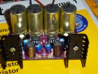
Manufacturing quality is excellent. The purple one looks very sexy.😀
Start sourcing components.
Planned to build at next week or two.
Manufacturing quality is excellent. The purple one looks very sexy.😀
Start sourcing components.
Planned to build at next week or two.
I also agree about the quality of the boards! I'm sourcing components now too, will be building soon!
analog_sa said:Many thanks to Coffin for graciously providing the sample boards.
May I join you?
Thanks, Coffin. 😎
Received my boards some days ago, good quality PCBs indeed.
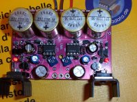
Well, as I needed a little more 'flexibility', I used 2.2K trimmers, paralleled with 10K 0.6W film resistors, for R2 and R12.
1K 0.6W film for feedback.
This way I can easily adjust for the range I wanted to, that is, between +/-12V and +/-18V.
I used one of the holes of the unused caps, C7 and C17.
The adjustment works well, but if I had space I would use a series resistor with the trimmer. Because the adjustment is wider than what I needed.
Also, I'm using the 5.0V LM336, and a lower gain on the op-amp (OPA627BP).
For ZD1 and ZD2, I'm using 10V/1W zeners.
EDIT: I'm using Elna Silmic 100uF/25V output caps. Diodes are MUR1100.
Here it is.
Attachments
I'm sourcing parts now.
I've decided to go with 24v for the positive board, for a headphone amp. I'm having a bit of trouble finding the 2SK170. Are there any possible substitutes? Or does anyone have some that'd be willing to sell me 5?
I've decided to go with 24v for the positive board, for a headphone amp. I'm having a bit of trouble finding the 2SK170. Are there any possible substitutes? Or does anyone have some that'd be willing to sell me 5?
bigmike216 said:I'm having a bit of trouble finding the 2SK170. Are there any possible substitutes?
I used 2SK170GR, but here's what you can use as substitutes:
2SK43, 2SK121, 2SK163, 2SK186
woops...
Sorry 'bout that--I was doing this from my feeble memory & thought you were talking about Q1, not Q5
The version I built (+/-75v) doesn't use a transistor there at all, but a resistor.
Sorry 'bout that--I was doing this from my feeble memory & thought you were talking about Q1, not Q5
The version I built (+/-75v) doesn't use a transistor there at all, but a resistor.
Coffin had posted it a few pages back, he has kindly directed my attention to that post. 🙂 Can't believe I missed it. 🙂
query
Hi, thought I'd check in here re; regulator boards, I sent the required postage/mailing address thru paypal 11-23 and haven't heard anything since then. Am anxious to try these w/chip amp project. Thanks in advance.
Hi, thought I'd check in here re; regulator boards, I sent the required postage/mailing address thru paypal 11-23 and haven't heard anything since then. Am anxious to try these w/chip amp project. Thanks in advance.
I got a sample PCB a while ago,now I am building a Krell KSA 50 clone and I found a trafo I could use for a regulared PSU for the front end...
How much current can the Mini reg give at +- 40v,if I change D1,D2,D11,D12 for 3A types,kan it give say 1-1.5 Ampere?
How much current can the Mini reg give at +- 40v,if I change D1,D2,D11,D12 for 3A types,kan it give say 1-1.5 Ampere?
Hi
The recommended output current is under 1A.
But you can try to set R6/R16 using the formula :
R6 & R16 can set the current , R6=R16
Max output I = Q1 hfe* ( 1.8V / R6 )
example : Q1 hfe=80 , R6&R16=200R , Max output I = 80* ( 1.8V / 200R ) = 720mA
cheers
Coffin
The recommended output current is under 1A.
But you can try to set R6/R16 using the formula :
R6 & R16 can set the current , R6=R16
Max output I = Q1 hfe* ( 1.8V / R6 )
example : Q1 hfe=80 , R6&R16=200R , Max output I = 80* ( 1.8V / 200R ) = 720mA
cheers
Coffin
Ryssen, please notice that the output voltage is the same as for the opamp. 40 volts is too much with most opamps. 30 or 36 V is max.
with most opamps. 30 or 36 V is max.
The OPA445 max voltage is +- 45v,the opamp was recomenden in the mini reg´s webpage.
I was told that the drivers for KSA50 would need max 0.5A per chanel,thats 1A for the regaulator if I make R6/R16 so I get 1Ampere max,doesn´t I need any headroom,just incase they would have to deliver more current?What will happend if I make the regulator deliver more than 1A?
Hi
Please change Q3/Q4 to 2SB649, Q13/Q14 to 2SD669.
mount them on the chassis to sink heat. don't forget to do the isolation.
Change R6/R16 to 75ohms.
It can afford 1.5A with no problem at all.
cheers
Coffin
Please change Q3/Q4 to 2SB649, Q13/Q14 to 2SD669.
mount them on the chassis to sink heat. don't forget to do the isolation.
Change R6/R16 to 75ohms.
It can afford 1.5A with no problem at all.
cheers
Coffin
Ok,thanks,I´ll have to find some BD types here in Sweden.Please change Q3/Q4 to 2SB649, Q13/Q14 to 2SD669
It will be 1-2 months before I can test the amp.
Notice that BD139/140 have different pinning 
I have some D44H11 and D45H11 if you want to test. If you really are goung to put 1-1.5 A through the BD's, it's a bit weak.
I have some D44H11 and D45H11 if you want to test. If you really are goung to put 1-1.5 A through the BD's, it's a bit weak.
- Home
- Amplifiers
- Power Supplies
- Mmini regulator (sample offering)