Hi everyone,
I've made the analysis of the main nodes using Tian probes, and the results are fine to me, but when I put a voltage source at the input (AC 1 0), I have a peaking at 50-60 MHz? Why? 🙁
Maybe the Tian probes are showing me wrong results, I've checked all main nodes, they seem fine and now I have this peaking, and I don't know it's origin. Can you help me?
PS: I'm still trying to understand why my headphones' amp has a VAS instability, do you have any idea? (If you don't know which amp I'm talking about check my last post). 🙁
Best regards,
Daniel
Attachments
-
Amp7_5_12_probe2_drivers_any.asc14.1 KB · Views: 59
-
BC3x7_40 Models.txt1.2 KB · Views: 55
-
Cordell Models.txt19.2 KB · Views: 45
-
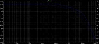
 50MHz_instability.jpg305.9 KB · Views: 149
 -
Amp7_5_12_probe5_drivers_any_voltage.asc13.8 KB · Views: 63
-
Amp7_5_12_probe4_drivers_any.asc14 KB · Views: 47
-
Amp7_5_12_probe3_drivers_any.asc14.1 KB · Views: 54
I've made the analysis of the main nodes using Tian probes, and the results are fine to me, but when I put a voltage source at the input (AC 1 0), I have a peaking at 50-60 MHz? Why? 🙁
All the results look fine to me too.
The peak at 50-60 MHz is way below 0 dB, this is not uncommon from feed forward or similar usually minor effects.
Such peaks are not a problem themselves but sometimes are a clue to some other problem.
I don't think that is the case here.
There is a minor effect that Tian probe does not consider.
The Middlebrook GFT probe (not the usual probe from 1975) does consider this and I will practice on your amp and see what I learn.
May take a while, I am not very familiar with it yet.
Best wishes
David
Hi Dave,
The peaking was caused by the improved current mirror, without it it doesn't appear.
Best regards,
Daniel
The peaking was caused by the improved current mirror, without it it doesn't appear.
Best regards,
Daniel
... caused by the improved current mirror, without it it doesn't appear.
Thanks for that, quite educational.
I have seen this mentioned in one of the Cordell threads, but didn't really think about it because I have only used simple current mirrors so far.
I think this is in line with my earlier comment - not a symptom of any problem, just a minor effect and your amp should be fine.
Best wishes
David
VAS instabilities in my headphones' amp
Hi everyone,
I'm also doing a smaller version of my MOSFET design, but with a BJT output to use as a headphones amp to incorporate in my project, but it seems to have a VAS instability related to the OPS I'm using, to have a little more stability I have to add a zobel network from base to collector in the drivers, I don't know if I want to use a capacitor in parallel with the VAS resistor, what I should do?
PS: LTSpice schematic attached
Best regards,
Daniel
Attachments
Hi David & Daniel,
I've also seen this positive phase shift, using Pspice with a Middlebrook'75 probe. I don't understand it either...
Hi Ian
I initially blamed this on a quirk of Spice.
Now I suspect it may be correct and the problem may be my faulty comprehension.
Have had any more ideas about this?
Best wishes
David
Hello David,
At the moment, I don't think I have any further (useful) information to add as to what causes the positive phase, but I have to admit, I haven't thought about it a great deal.
Other than, in my opinion, the plots where the loopgain phase is positive are still 'correct'. To measure the margins, I just use the 360 degree point, rather than 0 degrees.
Attached is an example plot. In this case, the phase margin is approximately 54 degrees (414-360), and the GM is approx 15 degrees (measured at the freq where phase=360).
Best wishes,
Ian
Attachments
Last edited:
...measured at the freq where phase=360...
Phase is a bit arbitrary of course.
And, like you, I found the "adjusted" value to be usable.
So it is probably "correct", in the sense it's mathematically consistent.
Perhaps the confusion arises because what I think of as polarity inversion is presented as a 180 shift and the phase looks to move the reverse of what I expect.
Write me if you have any more ideas, it bothers me that I don't quite understand such a basic issue.
Best wishes
David
I don't even find the frequency response routine in PSpice to be all that reliable - a circuit will look hunky-dory in simulation, then show all sorts of quirks near gain crossover when probed in reality with a gain-phase analyzer with sufficient bandwidth. PSpice doesn't account for parasitics unless you add them.
...phase analyzer with sufficient bandwidth. PSpice doesn't account for parasitics unless you add them.
Well, no Spice does parasitics unless you add them.
What analyser do you use?
Best wishes
David
I use the HP4194A... up to 40 MHz.
Nice. I expect that's at your job, or did you splash out?
Don't they run to 100 MHz?
Best wishes
David
- Status
- Not open for further replies.
- Home
- Amplifiers
- Solid State
- Minor Loop Stability Analysis for dummies