Yes. It is the introduction to a series on advanced amplifier techniques.
Next one looks at TPC, TMC, Output Inclusive and similar compensation schemes.
One after that is intended to cover how to check the amplifier, with simple V probes, Middlebrook 1975, Tian et al and Middlebrook "Final" probe techniques.
I plan to continue after that but better to write first and announce latter.
I can say objectively that the rest of the issue is definitely informative, I hope you like my piece too.
Best wishes
David
Hi David,
All sounds perfect to me. I look forward to vol 6 arriving. Your article is one of three that encouraged me to buy vol 6. Their subject matter fit in well with what I intend to try for my next (more advanced) amplifier. The first amp project has served me from an academic point of view. The next will have more bells and whistles.
Paul
Hi everyone, thank you for your help,
They are used to break the global NFB loop, I saw Michael Kiwanuka using them, but with a lower value. But if you think that's wrong, can you please tell me what I've to do?
PS: It's possible to create different frequency compensation schemes?
I only know, dominant pole compensation, output inclusive Miller compensation (I can't use this type of compensation, the amplifier will oscillate, but I know that many comercial amplifiers uses "IMC", also called Pure Cherry, like LM4766 IC for example), two pole compensation, transitional Miller compensation, I think that those last two can be bridged to have more phase margin at low frequencies, shunt compensation also known as lead lag compensation and the last one is Miller input compensation also called MIC, I've never simulated those last two. There is also a variant of dominant pole compensation with a zero added by a resistor in series with the Miller compensation capactior. My favourite form of compensation is BTMC a bridged transitional Miller compensation to have more phase margin at audio frequencies, but this increases the THD1 values 🙁
It's true that the 0dB point of the open loop gain should always be at 500kHz? I've mine at 2MHz (maybe a little lower), if I use 500kHz I've higher THD20 values, similar to the values produced by dominant pole compensation. 😕
There's any formula to calculate the TMC resistor?
I'm using f = 1/(2*pi*CMiller_series*Acl*Rltp) [Hz]
CMiller_series = 34 pF
Acl = 30 V/V
Rltp = 234R
Rtmc = 1/(2*pi*CMiller2*2*f) [ohm]
CMiller2 = 68 pF
f = 0.7 MHz
Rtmc = 1K7 (I'm using 1K8)
Best regards,
Daniel
Why are there 1GF capacitors connected to Q2 of the input pair?
They are used to break the global NFB loop, I saw Michael Kiwanuka using them, but with a lower value. But if you think that's wrong, can you please tell me what I've to do?
PS: It's possible to create different frequency compensation schemes?
I only know, dominant pole compensation, output inclusive Miller compensation (I can't use this type of compensation, the amplifier will oscillate, but I know that many comercial amplifiers uses "IMC", also called Pure Cherry, like LM4766 IC for example), two pole compensation, transitional Miller compensation, I think that those last two can be bridged to have more phase margin at low frequencies, shunt compensation also known as lead lag compensation and the last one is Miller input compensation also called MIC, I've never simulated those last two. There is also a variant of dominant pole compensation with a zero added by a resistor in series with the Miller compensation capactior. My favourite form of compensation is BTMC a bridged transitional Miller compensation to have more phase margin at audio frequencies, but this increases the THD1 values 🙁
It's true that the 0dB point of the open loop gain should always be at 500kHz? I've mine at 2MHz (maybe a little lower), if I use 500kHz I've higher THD20 values, similar to the values produced by dominant pole compensation. 😕
There's any formula to calculate the TMC resistor?
I'm using f = 1/(2*pi*CMiller_series*Acl*Rltp) [Hz]
CMiller_series = 34 pF
Acl = 30 V/V
Rltp = 234R
Rtmc = 1/(2*pi*CMiller2*2*f) [ohm]
CMiller2 = 68 pF
f = 0.7 MHz
Rtmc = 1K7 (I'm using 1K8)
Best regards,
Daniel
Attachments
Last edited:
...can you please tell me what I've to do?
Only what I have already recommended.
I find it effective to draw a simple block level schematic of the circuit to work out exactly what loop you want to probe. It's easier to be think clearly at this level about what you want to do.
Then the trick is to think about how to correctly place the Tian probe in the LTSpice ASC to examine that specific loop.
Correct placement means you should not have to "isolate" the loop with enormous inductors or capacitors, their use is both inaccurate and also prone to actual mistakes.
The Tian probe itself calculates and allows for forward and back transmission, so placement rather than attempted isolation is the key.
I would NOT use those capacitors.
I like to start with a simplified circuit with all the clutter removed, like the power supply capacitors that have no effect in your simulation because the V sources are perfect anyway, unused Spice directives, comments, protection circuitry. etc
Probe that to make sure each loop is OK.
That is, plot the Return Ratio for the outer loop, the OPS loop, the VAS loop.
That makes it easier to isolate an anomaly to a particular loop.
Your crossover frequencies look reasonably safe to me, so far.
Best wishes
David
Hi everyone,
Thank you very much for your suggestions Dave Zan they were very helpful,
I've removed all the components that don't influence the signal path, and I've uncovered an instability at the VAS caused by the degeneration resistor, you can see the instability in the file attached (Amp7_5_12_probe3_instability.asc), I solved the instability with a 33nF capacitor in parallel with the VAS degeneration resistor, and now the instability seems to have gone, I've also tried to test a beta enhanced cascoded VAS that it's said to have a poor stability, but something strange happens, the phase plot is weird, and I can't understand the Bode plot.
Resuming I wanted to know your opinion about the 33nF capacitor in parallel with the VAS degeneration resistor and why I can't correctly probe beta enhanced cascoded VAS? 😕
I'm also interested about your opinion about the other loops that I've tested.
I've removed all the input capacitors present in the non inverting and in the inverting input.
I've probed the nodes represented in page 90 figure 4.9 of Bob Cordell's book.
PS:
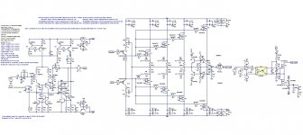
The attached picture is the complete amplifier with the capacitor added.
Thank you once more Dave Zan for your great help.
Best regards,
Daniel
Thank you very much for your suggestions Dave Zan they were very helpful,
I've removed all the components that don't influence the signal path, and I've uncovered an instability at the VAS caused by the degeneration resistor, you can see the instability in the file attached (Amp7_5_12_probe3_instability.asc), I solved the instability with a 33nF capacitor in parallel with the VAS degeneration resistor, and now the instability seems to have gone, I've also tried to test a beta enhanced cascoded VAS that it's said to have a poor stability, but something strange happens, the phase plot is weird, and I can't understand the Bode plot.
Resuming I wanted to know your opinion about the 33nF capacitor in parallel with the VAS degeneration resistor and why I can't correctly probe beta enhanced cascoded VAS? 😕
I'm also interested about your opinion about the other loops that I've tested.
I've removed all the input capacitors present in the non inverting and in the inverting input.
I've probed the nodes represented in page 90 figure 4.9 of Bob Cordell's book.
PS:
The attached picture is the complete amplifier with the capacitor added.
Thank you once more Dave Zan for your great help.
Best regards,
Daniel
Attachments
-
 Amp7_btmc3_hb5_s_bd12_prot_solid_state_output_relay.jpg193.9 KB · Views: 147
 -
BC3x7_40 Models.txt1.2 KB · Views: 46
-
Cordell Models.txt19.2 KB · Views: 45
-
Amp7_5_12_probe3_instability.asc16.7 KB · Views: 51
-
Amp7_5_12_probe3_cas.asc17.4 KB · Views: 52
-
Amp7_5_12_probe5.asc16.8 KB · Views: 52
-
Amp7_5_12_probe4.asc16.8 KB · Views: 47
-
Amp7_5_12_probe3.asc16.9 KB · Views: 58
-
Amp7_5_12_probe2.asc16.9 KB · Views: 45
Last edited:
Hi everyone,
I'm with doubts in Amp7_5_12_probe3 I don't know were to place the Tian probe, I don't know if I should put it after or before the compensation take off point, can you help me here please, and about the other nodes I'm doing it right?
The results are strange with a cascoded beta enhanced VAS and for dominant pole capacitor. Why?
Best regards,
Daniel
Hi Dave Zan could you please help me,
I don't know why I have to use that capacitor in parallel with the VAS degeneration resistor, but the LTSpice circuit Amp7_5_12_probe3, are showing instabilities, that can be solved this way, I'm doing something wrong in this circuit?
Best regards,
Daniel
I don't know why I have to use that capacitor in parallel with the VAS degeneration resistor, but the LTSpice circuit Amp7_5_12_probe3, are showing instabilities, that can be solved this way, I'm doing something wrong in this circuit?
Best regards,
Daniel
Hi Dave Zan could you please help me...
Yes, I have started to look at this.
Still some details I haven't worked out.
What VAS capacitor value?
Best wishes
David
Hi David thank you very much for your reply,
It's a 33nF capacitor that I've added in parallel with the VAS degeneration resistor, because I've noticed instabilities without it, the problem is that I've never seen an amplifier with a capacitor in parallel with the VAS resistor, I'm doing some mistake in my VAS minor loop analysis?
The file is attached in a previous post amp7_5_12_probe3.asc, could you please take a look?
Best regards,
Daniel
It's a 33nF capacitor that I've added in parallel with the VAS degeneration resistor, because I've noticed instabilities without it, the problem is that I've never seen an amplifier with a capacitor in parallel with the VAS resistor, I'm doing some mistake in my VAS minor loop analysis?
This is the subject of some discussion in the "TPC vs Cherry" thread.
It is recommended by some experienced people, Cherry especially.
I still do not understand all the complications.
Even Richard, despite his extensive experience, is a bit unclear.
So I have some work to do.
Best wishes
David
Hi David thank you very much for your great help,
Do you think that I'm doing the VAS analysis correctly?
And about the capacitor do you think that's a good idea, do you use it in your designs?
Best regards,
Daniel
Do you think that I'm doing the VAS analysis correctly?
And about the capacitor do you think that's a good idea, do you use it in your designs?
Best regards,
Daniel
...
Do you think that I'm doing the VAS analysis correctly?
And about the capacitor do you think that's a good idea?Yes, the analysis that I have checked looked fine.
I do think the capacitor can be helpful, but I have not worked out exactly how to optimize the circuit.
Best wishes
David
Hi everyone,
I've tested my amp without the bootstrapped drivers and know I don't have to use the capacitor in parallel with the VAS degeneration resistor. There's any problem with the bootstrapped VAS?
I've noticed that an amplifier could be locally stable in the VAS with the global NFB applied and unstable without it and vice versa, this is really strange, and another thing that I've discovered is that an amplifier with dominant pole compensation cannot be probed at the VAS with global NFB applied, otherwise I don't understand the results, the phase shift is positive 😕
With bootstrapped drivers the VAS also seem to have problems with the global NFB closed, and so I added the capacitor, when I looked at the VAS plot without global NFB applied (1GF at the inverting input) it was awful. Can you help me?
I also have an headphones amplifier with stability problems, and I don't know how to solve them, because I've peakings in the VAS plot when NFB is enclosed, with NFB open I don't have instabilities.
PS:
Please if you have time
Plot the tian probe for Amp7_5_12_probe3_drivers_dominant.asc to see dominant pole compensation issues and then plot with a 1GF capactor connected to the inverting input.
Plot the tian probe for Amp7_5_12_probe3_drivers.asc with a 1GF capactor connected to the inverting input.
Do both analysis with and without this capacitor for Amp5_v5_probe3.asc.
Best regards,
Daniel
Attachments
..I've tested my amp without the bootstrapped drivers and know I don't have to use the capacitor in parallel with the VAS degeneration resistor. There's any problem with the bootstrapped VAS?
I also discovered that your bootstrapped drivers are a source of unusual behaviour.
I have never tried this myself so it took a while to study
I recommend you drop them until the rest of the issues are resolved.
Then not only would the drivers be simpler but the VAS too.
Start simple and add complexity when you really understand.
Even apparently simple circuits have subtleties.
... I've discovered is that an amplifier with dominant pole compensation cannot be probed at the VAS with global NFB applied, otherwise I don't understand the results, the phase shift is positive 😕
I sometimes have this positive phase shift too.
It seems to be a quirk of LTSpice, or else I don't understand it either.
Anyone else informed about this?
With bootstrapped drivers the VAS also seem to have problems with the global NFB closed, and so I added the capacitor, when I looked at the VAS plot without global NFB applied (1GF at the inverting input) it was awful...
Unless you plan to add a 1GF capacitor to your actual amplifier then I don't think this is useful.
Why do you persist with this?
Best wishes
David
Last edited:
I sometimes have this positive phase shift too.
It seems to be a quirk of LTSpice, or else I don't understand it either.
Anyone else informed about this?
David
Hi David & Daniel,
I've also seen this positive phase shift, using Pspice with a Middlebrook'75 probe. I don't understand it either.
Another thing I don't understand is why I get different results If I put the probe between the VAS transistors (in a 2 transistor EF VAS) compared to at the base of the first transistor in the VAS. This may be explained by the fact that the impedance is high at the base of the first VAS transistor, whereas, it is low at the base of the 2nd VAS transistor. Another thought (possibly incorrect) is that there is bidirectional transmission associated with this first transistor base node, since the miller compensation cap is usually connected there.
My probe is sensitive to impedance and it is directional (as explained in the Middlebrook 1975 paper). I would expect that the LTspice Tian probe does not suffer from these limitations, so I am surprised to hear about the +ve phase shift with Tian. I would appreciate someone trying placing the probe between the VAS transistors and seeing if they get different results.
Also, when using a loopgain probe, I do not interfere with the circuit in any other way. In other words, I do not break other loops or make hi-Z, or low-Z any other nodes. Am I in error not doing so?
In short, I trust my loopgain sims with the probe placed at the amplifier output, but I have become suspicious at results with the probe placed at the VAS input base.
I have more to learn about these matters, and would greatly appreciate any more information or thoughts.
Best Regards,
Ian
Another thing I don't understand is why I get different results If I put the probe between the VAS transistors (in a 2 transistor EF VAS) compared to at the base of the first transistor in the VAS. This may be explained by the fact that the impedance is high at the base of the first VAS transistor, whereas, it is low at the base of the 2nd VAS transistor. Another thought (possibly incorrect) is that there is bidirectional transmission associated with this first transistor base node, since the miller compensation cap is usually connected there.
My probe is sensitive to impedance and it is directional (as explained in the Middlebrook 1975 paper). I would expect that the LTspice Tian probe does not suffer from these limitations, so I am surprised to hear about the +ve phase shift with Tian. I would appreciate someone trying placing the probe between the VAS transistors and seeing if they get different results.
The Middlebrook probe should be independent of impedance.
It is not independent of bilateral transmission.
Move to LTspice, then you can share your circuits,😉
Also, when using a loopgain probe, I do not interfere with the circuit in any other way. In other words, I do not break other loops or make hi-Z, or low-Z any other nodes. Am I in error not doing so?
On the contrary. I think you are correct and the other practice is inaccurate.
Like many misconceptions in audio, persistently passed on despite the evidence.
In short, I trust my loopgain sims with the probe placed at the amplifier output, but I have become suspicious at results with the probe placed at the VAS input base.
I tested the Tian probe to make sure placement did not matter.
In the first tests I did the results matched perfectly.
But this phase anomaly is a mystery at the moment, thanks for the input.
And I have a found a few other discrepancies.
I suspect the probe is correct and they reveal some useful information, some kind of "feedback leak", but I haven't had time to research this yet.
Best wishes
David
Hi David,
Thanks for your thoughts and for confirming that Middlebrook'75 is (or should be) independent of impedance.
I have re-read the last main paragraph of section 4 of http://www.ele.tut.fi/teaching/ele-3100/lk0809/tehol1/MiddleBrook75.pdf and the text suggests that the loopgain measurement may be in error ('inaccuracy is an inherent defect') for small T. I wonder if that is why I get differing results at the two VAS bases.
Also, the start of section 5, suggests that there IS a measurement error if Z2>>Z1 is not met(or vice-versa), suggesting that the probe of section 4 is still sensitive to impedance, hence, the double null technique of section 5.
As you can see, I don't know what to believe. 'The truth is out there', it is just a case of identifying (and understanding) it!
Another possibility is that the implementation of the probe I use is incorrect.
Thanks once again for any further input.
Cheers,
Ian
Last edited:
I have re-read the last main paragraph of section 4 of http://www.ele.tut.fi/teaching/ele-3100/lk0809/tehol1/MiddleBrook75.pdf and the text suggests that the loopgain measurement may be in error ('inaccuracy is an inherent defect') for small T. I wonder if that is why I get differing results at the two VAS bases.
Also, the start of section 5, suggests that there IS a measurement error if Z2>>Z1 is not met(or vice-versa), suggesting that the probe of section 4 is still sensitive to impedance, hence, the double null technique of section 5.
This is due to sensitivity to measurement inaccuracy.
It should not be an issue in a simulation.
I just checked with a Tian probe at the base of the first VAS transistor and between that EF and the base of the VAS second transistor.
Perfectly identical in LTspice
It seems the problem is in Pspice.
Best wishes
David
Last edited:
Thanks for confirming that David - much appreciated.
Attached are the results and schematics illustrating the strange difference.
(As an aside, if I use pure Cherry and add 270pF VAS degeneration caps, the difference between the two probe positions becomes even greater, with one of the positions indicating instability, and the other showing good margins - very odd indeed).
Cheers,
Ian
Attachments
Last edited:
This is due to sensitivity to measurement inaccuracy.
It should not be an issue in a simulation.
Best wishes
David
Ah, thanks for enlightening me.
Ian
...Attached are the results and schematics...
with one of the positions ...instability, and the other... - very odd indeed
That's unacceptably bad. Definitely time to move to LTSpice.
As if the ability to share your work wasn't already sufficient.😉
Best wishes
David.
- Status
- Not open for further replies.
- Home
- Amplifiers
- Solid State
- Minor Loop Stability Analysis for dummies