I'd estimate between about 80Hz and 500Hz or so (could be wrong, though, as this is based on the instruments that seemed to sound more realistic, and those all have overtones that might be causing real effects....). Another confounding this is that room modes are in play there. Listening is done pretty close to the speakers to reduce that, and the FIR eq was done with mic very close to the speaker. Justifying the reported valuation of this kind of subjective report.
Room treatment probably plays a role here. Your room has quite a bit of treatment.
Here's an anecdote:
When I first heard the Magic Bus, the track that really caught my attention was 'Billie Jean' by Michael Jackson. I'd heard the track a thousand times, and when Jon played it, my first impression was that it was a cover band. Because the recording sounded quite a bit different than what I was accustomed to. It took a full 10-15 seconds for me to realize that it *wasn't* a cover, it was the original track. But his Bus is so heavily treated, I was hearing the bassline in 'Billie Jean' in a way that I'd never heard it before.
I think that dipoles tend to do this too; with fewer room reflections, it tends to be very revealing of midbass rhythms.
But that opens up another can of worms, how do you measure phase when you have two sides of the cone radiating 180 degrees out of phase? Clearly the sound from the back of the cone is going to screw up the phase of the front of the cone, but somehow it still sounds good. I'd speculate that the answer has something to do with the precedence effect.
Wesayso - I'm trying to understand your point. Is the data that you show actual room measurement data? How is it so flat?
So how much overlap creates a minimum phase condition?
I don't understand your question. Do you mean how large the distance between the modes has to be to be two minimum phase phenomena? I don't know exactly. I quess it depends on the Q-factor of the modes.
Good discussion. The issue I am describing is driver time alignment. Here is what a step response of a typical 3 way system looks like:
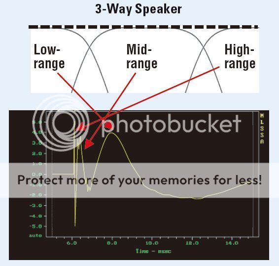
A combination of drivers, passive XO, and driver Z offset on the baffle produces a typical step response above.
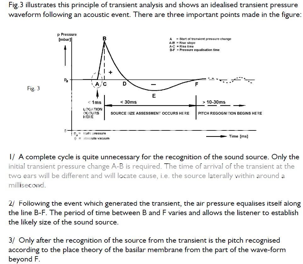
So what does an ideal step response look like? I have posted several examples on the forum, but this idealized transient pressure response in air is a good diagram in my opinion:
So how does one achieve that? A bit of progression if you will. When I started equalizing loudspeakers I was able to get a reasonable frequency response like the B&K house curve as example, but it still did not sound right to me. Moving to Digital Room Correction products offered more frequency response control and excess phase correction, which started to sound a lot better to my ears, and produced a fairly nice step response, but not quite right in two areas. One was there was always an edge to the sound or forward sounding in the image, like the tweeter always arriving first followed by the mids and then woofer, even with excess phase correction.
I finally ended up using digital XO (linear phase) and time aligning my drivers. This is finally sounded right to my ears in both tone, even though I was using the same target frequency response, and depth of soundstage. Meaning the sound stage did not sound discontinuous between the drivers and became point source like a single driver. I know, quite a subjective description, not to sure how else to describe it.
Here is the step response of my 3 way from the same measurement made in post #235 http://www.diyaudio.com/forums/multi-way/283068-mini-synergy-horn-experiment-24.html#post4553340
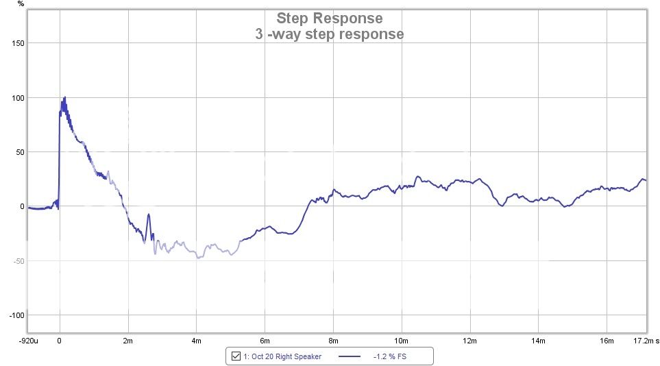
It's not the cleanest as I had a buzz/RF in the measurement chain. However, comparing it to the idealized transient response as posted above, it comes pretty close to matching. And has resulted in the best sound I have heard from my system to date.
The phase response in post 235 is basically flat at the listening position except for the coupla phase wraps in the low end due to a room mode. The group delay is also flat, except again at the room mode.
Meaning, I think it is a multitude of factors for achieving point source sound, good step response, flat phase, and ones preferred frequency response target at the listening position. I would love to be able to set up some objective listening tests to AB the difference between excess phase correction and time aligning the drivers with excess phase correction to see which is the real audible component.
PS. pre-ringing compensation in linear phase filters has been addressed by the majority of DRC players. Here is one example: http://files.computeraudiophile.com/2013/0620/AcouratePRCen.pdf
PPS. This paper on thoughts on XO's is what led me to using linear phase XO: http://files.computeraudiophile.com/2013/1202/XOWhitePaper.pdf
Hope some of that is useful.
A combination of drivers, passive XO, and driver Z offset on the baffle produces a typical step response above.
So what does an ideal step response look like? I have posted several examples on the forum, but this idealized transient pressure response in air is a good diagram in my opinion:
So how does one achieve that? A bit of progression if you will. When I started equalizing loudspeakers I was able to get a reasonable frequency response like the B&K house curve as example, but it still did not sound right to me. Moving to Digital Room Correction products offered more frequency response control and excess phase correction, which started to sound a lot better to my ears, and produced a fairly nice step response, but not quite right in two areas. One was there was always an edge to the sound or forward sounding in the image, like the tweeter always arriving first followed by the mids and then woofer, even with excess phase correction.
I finally ended up using digital XO (linear phase) and time aligning my drivers. This is finally sounded right to my ears in both tone, even though I was using the same target frequency response, and depth of soundstage. Meaning the sound stage did not sound discontinuous between the drivers and became point source like a single driver. I know, quite a subjective description, not to sure how else to describe it.
Here is the step response of my 3 way from the same measurement made in post #235 http://www.diyaudio.com/forums/multi-way/283068-mini-synergy-horn-experiment-24.html#post4553340
It's not the cleanest as I had a buzz/RF in the measurement chain. However, comparing it to the idealized transient response as posted above, it comes pretty close to matching. And has resulted in the best sound I have heard from my system to date.
The phase response in post 235 is basically flat at the listening position except for the coupla phase wraps in the low end due to a room mode. The group delay is also flat, except again at the room mode.
Meaning, I think it is a multitude of factors for achieving point source sound, good step response, flat phase, and ones preferred frequency response target at the listening position. I would love to be able to set up some objective listening tests to AB the difference between excess phase correction and time aligning the drivers with excess phase correction to see which is the real audible component.
PS. pre-ringing compensation in linear phase filters has been addressed by the majority of DRC players. Here is one example: http://files.computeraudiophile.com/2013/0620/AcouratePRCen.pdf
PPS. This paper on thoughts on XO's is what led me to using linear phase XO: http://files.computeraudiophile.com/2013/1202/XOWhitePaper.pdf
Hope some of that is useful.
John (Patrick) - Phase is unambiguous if done at a single point wrt the source signal. It wouldn't matter if it was a dipole or monopole.
When I heard the classical Orions, what struck me was the bass. It was exceptionally good. But it wasn't any better than what I get with multiple subs. The way I understand that to myself is that dipoles each act as two sources, so in essence a stereo dipoles are four sources and maybe that why it sound like my three source monopoles. The dipoles could not go as low as my monopole setup however.
But the fact is that, unlike common folklore, dipoles do not excite fewer modes, they just do it differently.
Wesayso - I'm trying to understand your point. Is the data that you show actual room measurement data? How is it so flat?
It is data that has been gated in REW with a 4 cycle frequency dependant window. This smooth's the data at about 1/6 octave. I use it to show the phase of the gated first wave hitting the listening spot. This is my left speaker. It's a living room with some treatment, but I cannot solve everything that way without getting in trouble with my spouse.
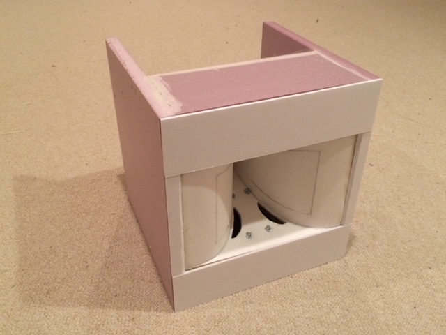
These are the speakers responsible for that FR:

I use FIR correction that is using a frequency dependant window for the correction. A lot of misconception surrounds FIR correction. I tested that before jumping in. It actually works quite well to measure at one (sweet) spot and apply a correction based on a short frequency dependant window. As has been said by others like Mitch for example.
Edit: the room isn't exactly the same as pictured, The stereo equipment has moved to the spot under the TV set and my right side now has the same look as the left on here with the cushions etc. The reason was the stereo equipment showed disturbances in my right speaker measurements.
Room treatment probably plays a role here. Your room has quite a bit of treatment.
Here's an anecdote:
When I first heard the Magic Bus, the track that really caught my attention was 'Billie Jean' by Michael Jackson. I'd heard the track a thousand times, and when Jon played it, my first impression was that it was a cover band. Because the recording sounded quite a bit different than what I was accustomed to. It took a full 10-15 seconds for me to realize that it *wasn't* a cover, it was the original track. But his Bus is so heavily treated, I was hearing the bassline in 'Billie Jean' in a way that I'd never heard it before.
I know how that feels... Most people including myself had a real strange look on their face when listening to that song in my room.
"They don't care about us" is another.... very powerful! Yet very different from what I remembered. I still hear many new things. But I don't have much physical treatment. 3 large panels. And no: these arrays do not sound like bloated images with huge lips 😉.
** maybe we should move all this talk to a different thread? Nate? **
Last edited:
Hi Mitch
I have a real problem with point #3 in you impulse response drawing. First an pure impulse does not have a "pitch" and second the time it takes to recognize pitch varies with frequency. Look at the impulse responses for gamma tone filters and you will see what I mean. It takes a long time for a LF pitch recognition to settle, but a very short time for HFs. Point #3 just goes against all of that.
But I do not disagree with your point about a "compact" impulse response. When things aren't arriving in time correctly they just don't sound right. I find that Griesingers explanation of this makes the most sense. But yet, most people here are reporting that only freq < 700 Hz are affected by the phase linearity, which contradicts what both of us are saying.
Wesayso - you are able to equalize out all of the modes and get a perfectly flat FR that is minimum phase. Is the filter to do that minimum phase in the modal region? And what do things look like away from that magic spot?
I don't understand your question. Do you mean how large the distance between the modes has to be to be two minimum phase phenomena? I don't know exactly. I quess it depends on the Q-factor of the modes.
Surely the distance between the modes is also a factor. What I do not understand is how a system with minimum phase modes all of a sudden becomes non-minimum phase. This just isn't like physics. Things don't happen all of a sudden (except in quantum mechanics.)
Two minimum phase electrical filters when added, even overlapped, are still minimum phase. What is so unique about room modes?
Crossovers are non-minimum phase because of offset of the drivers. This isn't the case of a monopole driver exciting room modes at LFs.
Geddes - Not all of them as is shown by the dip at 60 Hz. The right side has dips at other places and a stereo measurement adds favourably.

Left, right and both playing, again with a 4 cycle FDW. (you can see I add a little at 60 HZ in my right side to compensate for the left)
My filter uses linear phase parts to accomplish this. I use a combined set of parameters in DRC to get what I want. The other plot I showed was all linear. The difference in this one is that the Excess phase clean up stage was set to minimum phase.
I have done measurements on different spots along my listening couch. While they do show minor deviations, they average to the same curve as the one set at the listening position. It has taken me the bigger part of this year to find my "right" recipe. I do not use standard DRC templates to get there. I go out of the original intended scope of that program to get what I want.
First step is to optimise the room and speakers, digital processing cannot fix everything.
Last edited:
Good discussion. The issue I am describing is driver time alignment. Here is what a step response of a typical 3 way system looks like:
A combination of drivers, passive XO, and driver Z offset on the baffle produces a typical step response above.
So what does an ideal step response look like? I have posted several examples on the forum, but this idealized transient pressure response in air is a good diagram in my opinion:
So how does one achieve that? A bit of progression if you will. When I started equalizing loudspeakers I was able to get a reasonable frequency response like the B&K house curve as example, but it still did not sound right to me. Moving to Digital Room Correction products offered more frequency response control and excess phase correction, which started to sound a lot better to my ears, and produced a fairly nice step response, but not quite right in two areas. One was there was always an edge to the sound or forward sounding in the image, like the tweeter always arriving first followed by the mids and then woofer, even with excess phase correction.
I finally ended up using digital XO (linear phase) and time aligning my drivers. This is finally sounded right to my ears in both tone, even though I was using the same target frequency response, and depth of soundstage. Meaning the sound stage did not sound discontinuous between the drivers and became point source like a single driver. I know, quite a subjective description, not to sure how else to describe it.
Here is the step response of my 3 way from the same measurement made in post #235 http://www.diyaudio.com/forums/multi-way/283068-mini-synergy-horn-experiment-24.html#post4553340
It's not the cleanest as I had a buzz/RF in the measurement chain. However, comparing it to the idealized transient response as posted above, it comes pretty close to matching. And has resulted in the best sound I have heard from my system to date.
The phase response in post 235 is basically flat at the listening position except for the coupla phase wraps in the low end due to a room mode. The group delay is also flat, except again at the room mode.
Meaning, I think it is a multitude of factors for achieving point source sound, good step response, flat phase, and ones preferred frequency response target at the listening position. I would love to be able to set up some objective listening tests to AB the difference between excess phase correction and time aligning the drivers with excess phase correction to see which is the real audible component.
PS. pre-ringing compensation in linear phase filters has been addressed by the majority of DRC players. Here is one example: http://files.computeraudiophile.com/2013/0620/AcouratePRCen.pdf
PPS. This paper on thoughts on XO's is what led me to using linear phase XO: http://files.computeraudiophile.com/2013/1202/XOWhitePaper.pdf
Hope some of that is useful.
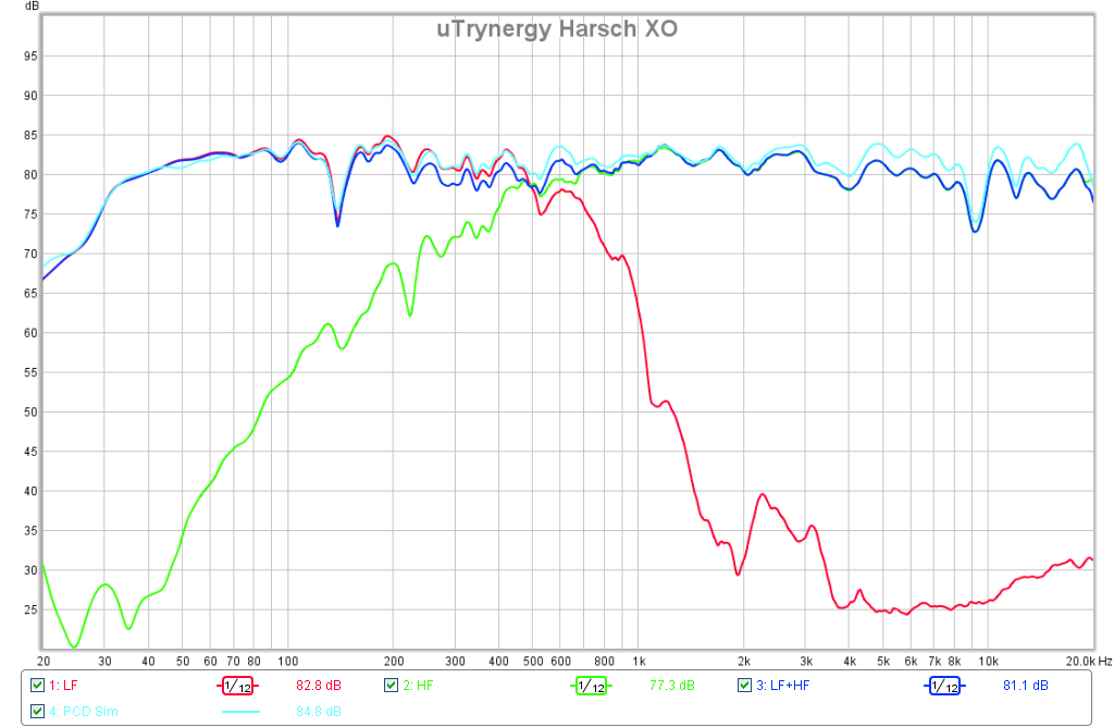
+1 on the proper Step Response for a speaker that sounds good. I have been a proponent of the Harsch XO that allows one to get kind of close to this ideal using only IIR filters. By combining a 4th order Butterworth low pass on the woofer and a 2nd order Bessel high pass on the tweeter with a time delay on the tweeter equal to half the period of one cycle at the XO frequency - one can get a triangle step response. It's the acoustical filter function that you need to follow to get this. Here is the latest from my two way Trynergy.
More on Harsch XO:
http://www.diyaudio.com/forums/multi-way/277691-s-harsch-xo.html
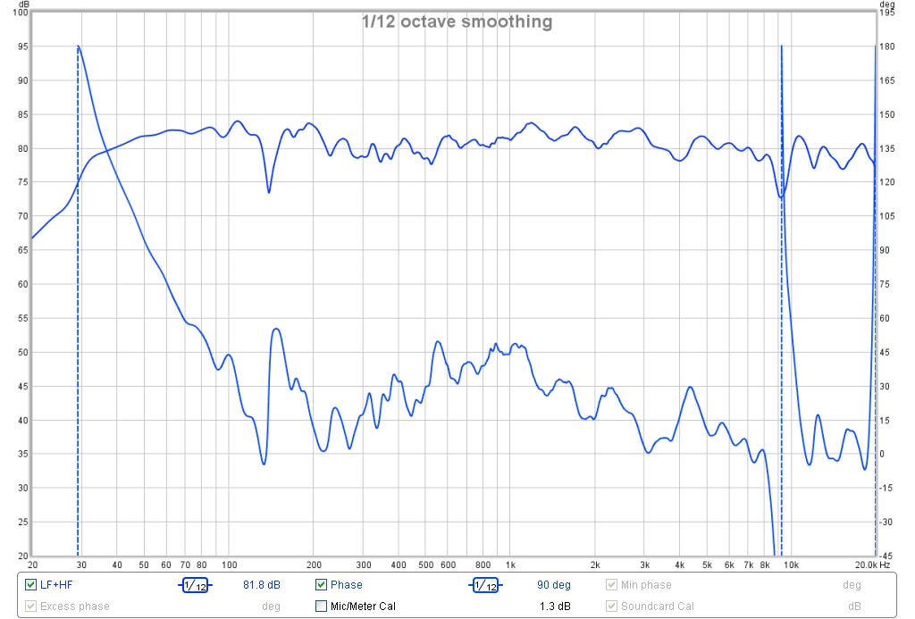
Here is the corresponding measures phase - relatively flat over 200Hz to 8kHz range:
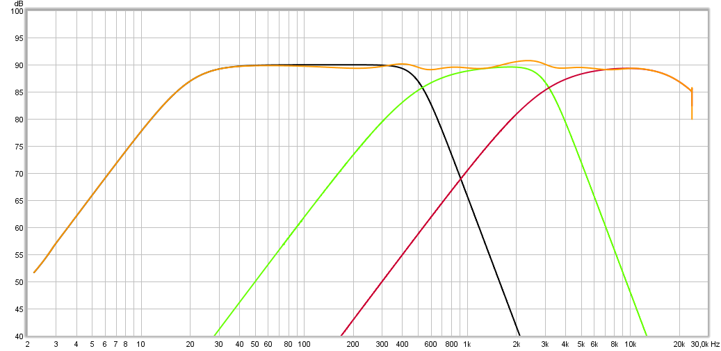
And here is the acoustical xo:
More here on this speaker:
http://www.diyaudio.com/forums/full...trynergy-full-range-tractrix-synergy-122.html
Recently, Byrtt has shown via electronic loop back simulations that the Harsch can be applied to a 3 way by cascading the filter slopes as follows:
Gives this Step Response:
When a speaker is time aligned correctly like this, the percussion sounds live and very realistic. The sad fact is - most speakers are not properly time aligned and people don't know what they are missing because they don't know what they don't know. However, once you get your speakers to sound like this - you can't go back.
Last edited:
So what does the ideal STEP look like? For that I look at a loop back of my DAC signal back to the REW microphone input with a simple cable and do a sweep. When I do that I get this graph:
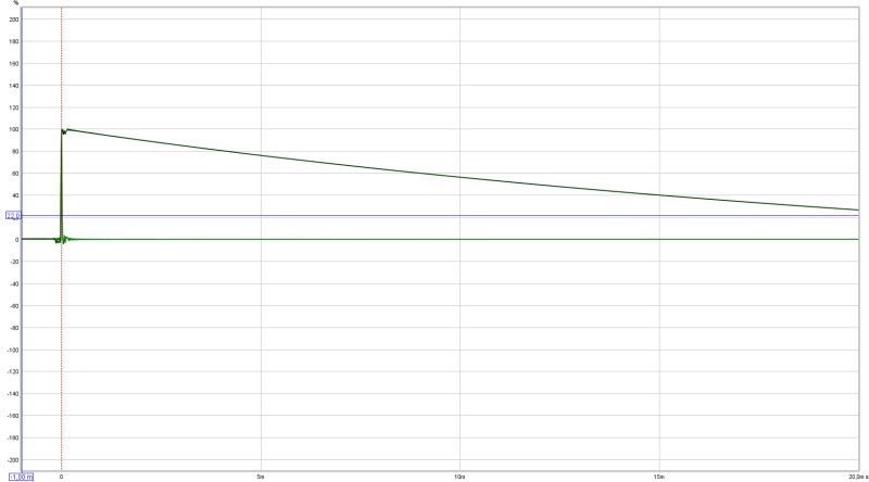
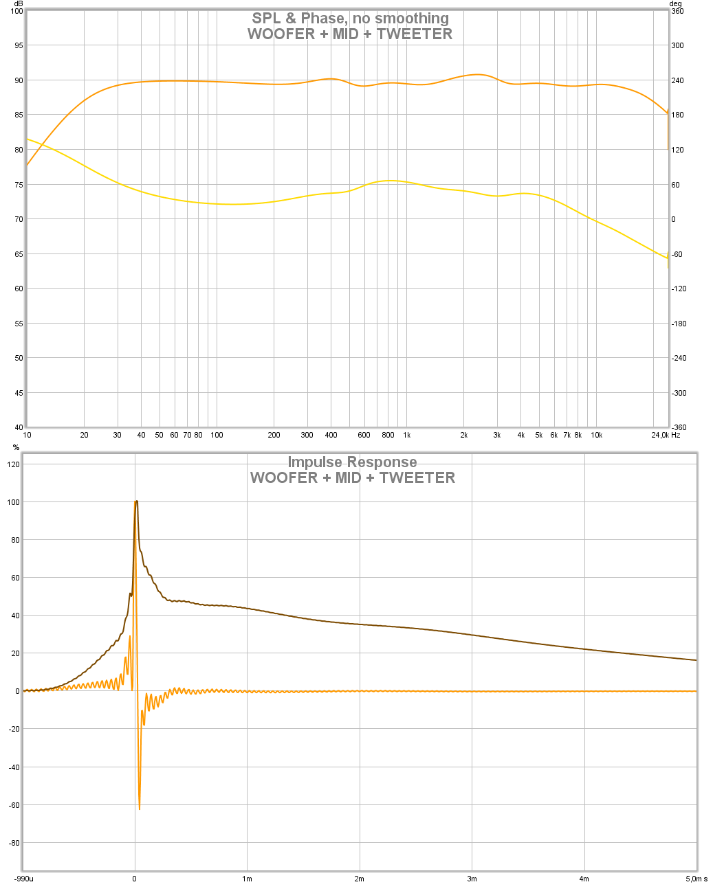
When I set everything in my processing chain to linear phase with a flat response I get this:

Not entirely the same, but close. I do not listen to this (though obviously I tried it) I have a preferred room curve that has been discussed on another thread and as shown I have the "Excess phase removal" stage set to minimum phase.
What I actually listen to looks like this:

And has a wavelet result (of the stereo pair) that looks like this:

Not bad results in a living room I'd say. As measured at the listening position.
I can show a result deeper than -20 dB but that will show you the ugliness of my room 😀.
When I set everything in my processing chain to linear phase with a flat response I get this:
Not entirely the same, but close. I do not listen to this (though obviously I tried it) I have a preferred room curve that has been discussed on another thread and as shown I have the "Excess phase removal" stage set to minimum phase.
What I actually listen to looks like this:
And has a wavelet result (of the stereo pair) that looks like this:
Not bad results in a living room I'd say. As measured at the listening position.
I can show a result deeper than -20 dB but that will show you the ugliness of my room 😀.
Wesayso
Pretty impressive.
If I understand you correctly then you have neutralized the modes with a minimum phase filter which means that all the modes are minimum phase and not like what was being claimed above.
Pretty impressive.
If I understand you correctly then you have neutralized the modes with a minimum phase filter which means that all the modes are minimum phase and not like what was being claimed above.
** maybe we should move all this talk to a different thread? Nate? **
No it's fine with me and I think applies to the Synergy concept. I'm all for a thread split though if anyone thinks it might be easier to search/reference the info in the future.
Geddes - That should be about right, yes. Though the DRC process still works in the time domain to clean up the (early) signal. It also largely takes care of the time smear at higher frequencies (inherent in Arrays) judging by filtered impulse plots (filtering by frequency).
An unfiltered IR shows (way more) ringing after the main pulse. Comb filtering does occur however. No way around that.
I looked at every available way in REW to view my unprocessed impulse to see what happens and at what time. Many nights were spend to find answers. That eventually gave me a clear picture of what parts of the plots happened in the first arriving wave front and what parts are actually due to the room in one way or another (and should be left alone as much as possible).
Being large line arrays helps take care of floor and ceiling reflections. Some well placed damping panels help at other first reflections. My entire focus was to clean up everything in the first 20 ms. No high SPL level early reflections.
I guess the large area of the cones in the arrays help act somewhat like a distributed source for bass. I have no subs. Yet the bass measures flat in a very large area. Very even distribution.
At least that's what I make of it. Hope I chose the right words here. That's not always easy.
Thanks for the platform 😉. I think/feel this is an interesting discussion for all of us.
Ahh, thanks BYRTT 😀
An unfiltered IR shows (way more) ringing after the main pulse. Comb filtering does occur however. No way around that.
I looked at every available way in REW to view my unprocessed impulse to see what happens and at what time. Many nights were spend to find answers. That eventually gave me a clear picture of what parts of the plots happened in the first arriving wave front and what parts are actually due to the room in one way or another (and should be left alone as much as possible).
Being large line arrays helps take care of floor and ceiling reflections. Some well placed damping panels help at other first reflections. My entire focus was to clean up everything in the first 20 ms. No high SPL level early reflections.
I guess the large area of the cones in the arrays help act somewhat like a distributed source for bass. I have no subs. Yet the bass measures flat in a very large area. Very even distribution.
At least that's what I make of it. Hope I chose the right words here. That's not always easy.
No it's fine with me and I think applies to the Synergy concept. I'm all for a thread split though if anyone thinks it might be easier to search/reference the info in the future.
Thanks for the platform 😉. I think/feel this is an interesting discussion for all of us.
wesayso not sure if output signal will be true to input with that mess 🙂.
Ahh, thanks BYRTT 😀
Last edited:
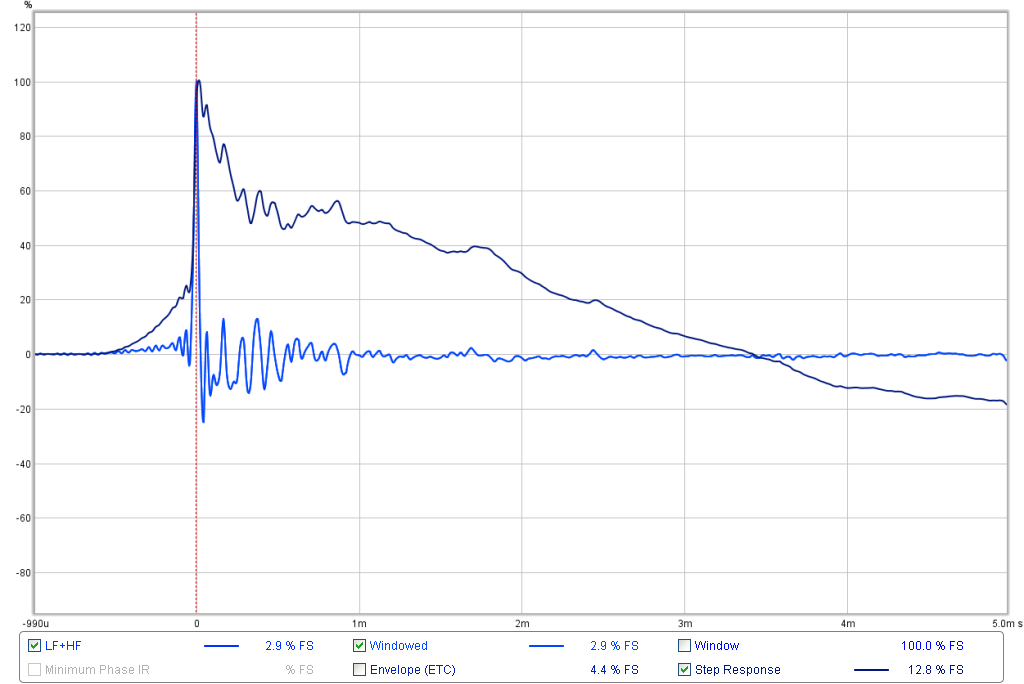
FWIW, and going back to the point of the "ideal" target, the step response of a minimum phase low pass filter looks like the graph you prefer rather than the linear phase example. This is a 20Hz BW2 LPF.So what does the ideal STEP look like? For that I look at a loop back of my DAC signal back to the REW microphone input with a simple cable and do a sweep. When I do that I get this graph:

I guess your DAC might roll off much lower than 20Hz which would be a reason for a relatively slow decay (but still the same shape so hard to tell from the graph posted)
Last edited:
3ll3d00d - Yes, thanks for that plot. Combine that with my HF response and my preferred downward FR room curve and you get the shape I posted.
Basically I created/formed (not sure of the right word here) something that acts as a "huge full range driver" out of the array with minimum phase behaviour and response from 17 Hz to 17 KHz with generous help from DSP. But don't forget the room if you try any of this.
As a concept, this probably should/could work on a Synergy horn as well. It already acts much like a single driver to begin with. If I hadn't build the arrays a Synergy horn would have been my choice. The arrays have the advantage of taking up hardly any floor space. That had the biggest Waf factor, despite their size. I guess I'm lucky.
You guys are too kind!
Basically I created/formed (not sure of the right word here) something that acts as a "huge full range driver" out of the array with minimum phase behaviour and response from 17 Hz to 17 KHz with generous help from DSP. But don't forget the room if you try any of this.
As a concept, this probably should/could work on a Synergy horn as well. It already acts much like a single driver to begin with. If I hadn't build the arrays a Synergy horn would have been my choice. The arrays have the advantage of taking up hardly any floor space. That had the biggest Waf factor, despite their size. I guess I'm lucky.
Yes, mess indeed. 🙂
He's just show boating now.
You guys are too kind!
Last edited:
Thanks for the on axis normalized plot. RThe goal with that is to get an vfidea of directivity relative to the 0 axis. For me, it says something. Looking at normalized and original helps give a clearer picture.
VWc
- Home
- Loudspeakers
- Multi-Way
- Mini-Synergy Horn Experiment