Freddi,On the cheap, could a Delta 10 make a horn driver? - its got a rather nasty peak before HF rolloff but is kicky in a K10. for little Karlsons, I'm looking at some of the B&C 10"
although qts is moderate, a Commonwealth 12 might make a decent horn driver (?)
Eminence Beta, Delta and Kappa 10" can all do well in horns if crossed over fairly steeply below their breakup peaks.
The Commonwealth 12 with only .7mm Xmax will do well if you "likes overdrive" 😉.
Art
12lta gets some mighty bragging over at diyaudio and i think it still has only 0.08" physical overhang 😀 (?) what causes the HF peak in Delta10a/b? - would a dustcap swap have little effect? (Delta 10A by itself sounds hellish under pink noise)
how much overhang is there in the old Altec 421? http://img76.imageshack.us/img76/4338/71hzwjpgfe5.jpg
how much overhang is there in the old Altec 421? http://img76.imageshack.us/img76/4338/71hzwjpgfe5.jpg
Last edited:
EVM15L is real wide range for a 15 and sounds clean up to 500-600 cycles. It can fit in a horn system where you need a driver to stretch a wide range and don't have or want a big horn.
I use the outrageous massive Celestion BX15 -4085 😀 in my midbass horns though because up to 300-400 where i use them they are perfect in my horns -
For bass horns below 80 I use four JBL 2225 and for subbass I use JBL 2242 in one mono center horn and two EVM18B in two sub corner horns - also a near field sub direct radiator delayed behind me loaded with EV DL18's. The bass is very clean, real and defined.
The HF peaks are probably cumulative effects from cone, dustcap, suspension, and strong motor, having done little experimentation with modifying speakers I could not tell you if replacing the dustcap alone would do much.what causes the HF peak in Delta10a/b? - would a dustcap swap have little effect?
I was thinking about the Commonwealth and Delta Pro drivers too...in terms of numbers they seemed to be 'close', but there's no way I can set money aside to 'test'!
An externally hosted image should be here but it was not working when we last tested it.
Above horn length 90 cm (3 feet) 3 sq feet hornmouth, 12 inch driver. Time cycles at 500 Hz begin to overlap each other, diffence down to 50 cm. Now i am gone try a 15 inch and try to move the driver closer to the front of the cabinet. Hope to get overlapping "times" with a 80 cm horn and the driver way back in front of the cabinet.
The fold in the upper and lower corner is 7.2 cm with a diagonal fold. That should be good to 500 Hz.
Freddi,
Eminence Beta, Delta and Kappa 10" can all do well in horns if crossed over fairly steeply below their breakup peaks.
The Commonwealth 12 with only .7mm Xmax will do well if you "likes overdrive" 😉.
Art
🙂
I think I personally am going to be using an active crossover, so I should be able to manage that roll-off. The use of horns really gives me a chance to experiment with EQ, pass bands, and any delay work that's required. I might have to take a trip to the pawn shop a couple of times this year to see if I can find any stereo amps so I can run one for each 'range pair'.
http://www.jblpro.com/pub/obsolete/low_frequency_enclosures2.pdf
"usable response to 45hz with maximal loading above 200hz"

Phenoholic Anonymus, I can't see your pictures....................
Norman
"usable response to 45hz with maximal loading above 200hz"

Phenoholic Anonymus, I can't see your pictures....................
Norman
Hi,
Does this work? I am having some trouble finding a good free image host. If i post the picture, everything works.
I have been working on the horn pathlength and driver diameter, above is the last result, horn lenght 90 cm, 12 inch with 500mm distance in time left between the mid and the woofer. I reckon with some more "design" i can close the gap between woofer and mid. At least on paper 🙂
Does this work? I am having some trouble finding a good free image host. If i post the picture, everything works.
An externally hosted image should be here but it was not working when we last tested it.
I have been working on the horn pathlength and driver diameter, above is the last result, horn lenght 90 cm, 12 inch with 500mm distance in time left between the mid and the woofer. I reckon with some more "design" i can close the gap between woofer and mid. At least on paper 🙂
Last edited:
I think for mechanical alignment (assuming for 6db and 24db), the mid and tweet (red line) will be a bit behind the back wall of the bass bin.
I am really getting close with the mechanical alignment and the folded W bin. Hornlength 90 cm, woofer 45 cm "before" the mid and tweeter "timeline" in the W-bin. Looks good on the drawing board. Now i will keep pushing buttons on the computer till the upper and lower corner diagonal gets small enough to pass 600 Hz /8 = 7.1 cm. Keep adding Hyperbole 🙂 Maybe a small 1 liter chamber before the woofer enters the horn.
Last edited:
Hey guys,
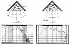
One thing I think will be helpful when designing a folded horn, especially a bifurcated one, is the final radiating angle the mouth has. This is best explained by reading the work done by Paul Klipsch and Roy Delgado on the Jubilee bass horn. See AES Volume 48 Number 10, October 2000. When you restrict the radiating angle you get an additional boost in high frequency output as the horn’s directivity continues to narrow in the high frequencies. The attached graphic is of the original Jubilee prototype with an included mouth angle of 72 degrees compared to the final design that has an included mouth angle of approximately 30 degrees. Both horns in this example are using the same drivers. This reveals that horn folding geometry and driver mass roll off are not the only important factors in getting high frequencies out of a folded horn. I built a “baby Jubilee” prototype using two Eminence Delta-8B drivers. The mass roll off of the Delta-8B is around 530Hz, however the prototype had its -6db point at 1330Hz on axis. While those numbers look really great, you must understand that the beam width is very narrow up that high. There are always tradeoffs.
One thing I think will be helpful when designing a folded horn, especially a bifurcated one, is the final radiating angle the mouth has. This is best explained by reading the work done by Paul Klipsch and Roy Delgado on the Jubilee bass horn. See AES Volume 48 Number 10, October 2000. When you restrict the radiating angle you get an additional boost in high frequency output as the horn’s directivity continues to narrow in the high frequencies. The attached graphic is of the original Jubilee prototype with an included mouth angle of 72 degrees compared to the final design that has an included mouth angle of approximately 30 degrees. Both horns in this example are using the same drivers. This reveals that horn folding geometry and driver mass roll off are not the only important factors in getting high frequencies out of a folded horn. I built a “baby Jubilee” prototype using two Eminence Delta-8B drivers. The mass roll off of the Delta-8B is around 530Hz, however the prototype had its -6db point at 1330Hz on axis. While those numbers look really great, you must understand that the beam width is very narrow up that high. There are always tradeoffs.
Attachments
Could that horn be built with a single Delta 8B?
The 30 degree dispersion angle wouldn't be that much of a problem for me, as the speakers are going to be used for a specific purpose, with a specific listening position.
The 30 degree dispersion angle wouldn't be that much of a problem for me, as the speakers are going to be used for a specific purpose, with a specific listening position.
1) Yes.1)Could that horn be built with a single Delta 8B?
2)The 30 degree dispersion angle wouldn't be that much of a problem for me, as the speakers are going to be used for a specific purpose, with a specific listening position.
2) You would want to match the 30 degree mid dispersion angle with a 30 degree high dispersion angle.
However, the 30 degree mid angle is not a smooth, even dispersion, as it is emanating from two sources (the left and right portion of the split horn) separated by more than a wavelength at the upper frequencies of operation.
Off axis response is choppy.
Hi unaHm,
I do not know if you started out with Hornresp yet. With this online calculator you can easily see what happens when you double (2 x Delta 8B) the hornmouth with respect to length etc. It's a simple but insightfull tool. In the end there is no way around Hornresp, but for a quick check if a 40Hz horn will be do-able with a 8 inch driver...
I would be more than happy to get some more info on horn directivity calculation. The Jubilee directivity difference is very interesting.
Thanks Phenoholic Anonymus - I may allow you to do that 🙂
I've played with Hornresp a little, but I don't yet know enough about the curve types (and their suitability for certain frequency ranges), and all of the numbers leads me to feel like I'm guessing!
I've played with Hornresp a little, but I don't yet know enough about the curve types (and their suitability for certain frequency ranges), and all of the numbers leads me to feel like I'm guessing!
Could someone help me out with this formula?
F = kk / α * w Where α = included wall angle, kk = 25.306 x 10³ and w = mouth width (metres)
For example on the Klipsch Jubilee. Or a La Scala bassbin? Just need to see the numbers and the method. So i can picture it
F = kk / α * w Where α = included wall angle, kk = 25.306 x 10³ and w = mouth width (metres)
For example on the Klipsch Jubilee. Or a La Scala bassbin? Just need to see the numbers and the method. So i can picture it
The given formula is for a conical expansion, the Jubilee and La Scala expansion is more exponential, and therefore go lower in frequency for a given mouth size, but the formula is for -6 dB pattern control, not low frequency cutoff.Could someone help me out with this formula?
F = kk / α * w Where α = included wall angle, kk = 25.306 x 10³ and w = mouth width (metres)
For example on the Klipsch Jubilee. Or a La Scala bassbin? Just need to see the numbers and the method. So i can picture it
The constant Kk is 25,306, using 25.306 makes one think horns would need to be 10 times larger 😉. 10³ is 1000.
Rod explained it, and gave an example on the same page:
"At the lower end if we for instance want a lower cut off frequency of 1500Hz and an angle of 90°, then from Keele's formula the diameter is ...
25,306 / ( 1500 * 90 ) = 0.187meter "
You can make easy comparisons using different types of horn expansion in Hornresp.
Conical horns are constant directivity, the included angle of the horn walls equal the -6 dispersion angle.
Exponential and all the other curved wall horn types narrow in dispersion as the frequency rises.
Art
Hmm, I'm use to seeing it in inches, which gives a little different result, but this is the mouth's included angle F6 frequency.
Don't know the Klipsch wall angles offhand, so let's say a horn has a 90 deg included angle that measures 1 m across it, then its F6 = [25.306*10^3]/[90*1] = 281.178 Hz.
The popular one in inches: F6 = 10^6/[90*39.37"] = 282.22 Hz
GM
Don't know the Klipsch wall angles offhand, so let's say a horn has a 90 deg included angle that measures 1 m across it, then its F6 = [25.306*10^3]/[90*1] = 281.178 Hz.
The popular one in inches: F6 = 10^6/[90*39.37"] = 282.22 Hz
GM
1) Yes.
2) You would want to match the 30 degree mid dispersion angle with a 30 degree high dispersion angle.
However, the 30 degree mid angle is not a smooth, even dispersion, as it is emanating from two sources (the left and right portion of the split horn) separated by more than a wavelength at the upper frequencies of operation.
Off axis response is choppy.
Thanks for the information Art! I bet that you've already considered it, but I was wondering if there would be any benefit to re-combining the horn paths at the front of the speaker. Would you gain anything in terms of mitigating the problem of having two sources?
That lead me to thinking more of a similar internal design to that of the T18, where the driver is placed roughly in the centre of the cabinet, and then the horn's path follows a 'snail shell' curve. I'm sure that this has also been considered, and given the (much shorter) needed length of the horn for midrange applications, I'd guess that there wouldn't be enough horn to fold.
My budget has altered, slightly, in that I might be able to afford a pair of Eminence Delta 10A speakers. With that in mind, I've re-visited the avenue of the Pi speakers mid horn that was mentioned earlier in this thread.
Before I continue, however, are there better solutions for the price (~$160 for a pair), and thusly a different horn design that might be more suitable?
- Status
- Not open for further replies.
- Home
- Loudspeakers
- Multi-Way
- Midbass horn