Thanks for your reply. Do I have to be on a computer or laptop? I’m trying with an iPad and still get and error on the pages?I can still download birkbott's BOM from few posts above (left click on it)
I’m trying on an iPad. I’ll try from my puter tonight but unfortunately it’s a Macbook, so we’ll see. Thanks for letting me know
Hi, what's the recommended Modushop case for this, and does anyone have any cad drawings they maybe willing to share for panel cutouts?
Thanks
Thanks
Works on a 2014 iMac Retina running OS10.6.8I’m trying on an iPad. I’ll try from my puter tonight but unfortunately it’s a Macbook, so we’ll see. Thanks for letting me know
Attachments
I finally resumed assembly of my Mez. With everything hooked up, I am getting voltage drops of 1.7 and -1.45 across R68, voltage of 9.71 and -10.69 at mid-board and DC offsets of -.002 on both channels (hearing 12V relay click) and everything looks fine. I am even able to see the A/C audio signal at the outputs.
However, once I connect an RCA cable to the output, the negative side LED bank (5 leds) goes dark and DC offset jumps to .165. I have the RCA connected to one of my ACA amps. It only happens if the power cable to that amp is plugged in. It does not happen if the terminating end of the RCA is not plugged into the amp. Also, I noticed that LED bank briefly went dark when I connected the input RCA cable, but came back. I did already remove all of the LED in that bank and tested them for basic function (they lit up to a 9V battery and 2KR).
Where should I be focusing my troubleshooting efforts?
First see if there is healthy 3-4V Vgs in the negative side's Mosfets and 0.5-0.7V Vbe in its BJTs. But it also looks like an issue of incompatible grounding between units. You could recheck the phasing of the DCB1's transformer secondaries as well.
Last edited:
It was indeed reversed phasing of the transformer secondaries. Thanks Salas. Final product really sounds amazing!
I’ve finally gotten my DCB1 into a chassis, and am at the testing phase. I purchased the Mez pcb in 2010… well one mustn’t rush perfection right? 😉 I usually have success straight away with most DIY projects, but sadly this one has proven to be the exception.
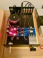
I’m using a 2 x 15V 50VA transformer, MUR860 diodes, CCS resistors are 7.5R, transistors are bolted directly to the 2mm thick chassis of a Naim ‘shoebox’ chassis copy via ceramic insulators. All LEDs and the Omron 12V relays were from Ed Fontaine’s orginal group buys here, and the matched 2SK170s were from Spencer’s group buy, also from here.
I’m getting no output from it at all into my Quad 606. No hum or hiss. When I turn it off, I can hear a relay (pretty sure the output relay) click, but cannot hear any click when turned on which is possibly the issue?
Powering on all the LEDs light up. The 500mA (247V mains here) fuse doesn’t blow, and nothing is getting hot. So hoping it’s something reasonably simple to trace, or (more likely) a silly mistake I’ve made.
Voltages are 9.86V and -9.83V - ‘leg trick’ implemented. Output of the 7812 relay regulator is 11.32V. Was wondering if that’s too low perhaps for the input selector relays to function?
Attachments
Last edited:
Hi, I would first suspect either a relay circuit error or the signal connectors in this.
Disconnect the DCB1 from other equipment, power it on, check continuity from the selected RCA Input to vol pot's input pin with the DMM buzzer. If it beeps all the way through it's not about the signal route or the input relay energizing selector wiring and its connector.
Then check continuity between the output relay's input to output pins and to output RCA.
Let me know.
Thanks for your suggestions Salas.
Input : There’s no continuity at all from either RCA input to volume pot’s input when switched on. I cannot hear any relay clicking either.
Output : With the unit off, I noticed that with multimeter probes on both the left and right output pads (the volume pot output pads on the pcb) it gives a continuity beep. So left and right signals must be shorting somehow, unless the output relay shorts them when not energised? I tested this with the output wiring unplugged from the board too, to rule out the wiring. I didn’t test further with the unit powered up after this, thought I’d best wait for your reply first.
As an aside I checked each relay diode was receiving 12V (11.3V in my case) and they are.
Investigate if the input selector and its connector are correctly wired and making contact. What the selector does is assigning ground continuity to each input relay consecutively. Closing DC circuit for each selected input relay's coil.
In the very old boards (single sided) the output relay was cutting signal outputs in series, but this board looks newer (double sided)? If so, that relay defaults signal outputs to ground when at rest.
In the very old boards (single sided) the output relay was cutting signal outputs in series, but this board looks newer (double sided)? If so, that relay defaults signal outputs to ground when at rest.
In other words the input selector's pole should be wired to gnd connector pin. Last of the six noted on the silkscreen.
The LM7812 should need a little sinking aid when it will power two relays at the same time (one in, output). Its 22V rail will augment its dissipation.
The LM7812 should need a little sinking aid when it will power two relays at the same time (one in, output). Its 22V rail will augment its dissipation.
Yes the selector switch wiring is all good. Just unplugged it from the board and checked continuity at each turn/click (4 inputs in my case). I did try a simple jumper cable on the pcb selector too, to rule out the selector assembly, but same result.
Next I’ll make sure there’s continuity between each Molex pcb selector pin, and the anode side of each associated relay diode, just to ensure I didn’t do anything really silly like not soldering all seven pins underneath! Will sink the 7812 as well, though it barely got warm in the brief tests I’ve done so far.
The board is 10 years old, but double-sided and has the ‘T’ output ‘mod’ incorporated, so the later pcb design I assume.
Could a dodgy BC550 or BC517 in the LM7812 area of the pcb cause the relay issue I have? Cannot remember now the brand I used. The BC550 is a ‘B’ grade, and I’ve just noticed the BOM states a ‘C’ grade to be used?
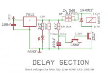
When you establish that signal reaches the volume pot's input and exits the pot, yet no sound at the main output, output relay is next suspect. But you said it clicks which is a positive sign. Anyway, here are the voltages to check in its circuit. Omron, NAIS, NEC/KEMET, all have the same properties.
Attachments
- Home
- Amplifiers
- Pass Labs
- Mezmerize DCB1 Building Thread