Thanks Salas. I'm going to try and match them, but I need a larger pool for sure. I'd much rather just buy matched sets, so may check out those contacts you mentioned too.Also read post #1518
Only try match Idss for the audio signal quad. Full matching like that quad having 100% same tracer curves is not required.
That was my intent. Just Idss.Only try match Idss for the audio signal quad. Full matching like that quad having 100% same tracer curves is not required.
I'm building the Mezmerize, B-1 Buffer. I will using 12vDc relays as specified. However, I'm still not clear on whether I jumper both 300R resistors and/or both 600R locations.
Thanks,
Rick
Thanks,
Rick
Those are paralleled. Put one jumper across where it says "note" in a resistor symbol. Its enough.
Hi
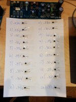
I followed Andrew T's Jfet Idss matching method below.. My results below..
The mesmerize Jfet states matching -up to 5mV DC offset-
First time I've done this matching..It would appear that my 20 fets look closely matched in the medium Idss range..
Any comments?
I followed Andrew T's Jfet Idss matching method below.. My results below..
The mesmerize Jfet states matching -up to 5mV DC offset-
First time I've done this matching..It would appear that my 20 fets look closely matched in the medium Idss range..
Any comments?
__________________I use DVM to take all my measurements. I don't trust ammeters.
A 9V pp3 and a 100r resistor is great for batching jFETs.
use a croc clip or inline socket to short together the G & S.
Apply +ve battery to 100r. Connect 100r to Drain of NjFET
Apply -ve to G+S
A low Idss jFET that draws ~0.5mA will drop ~50mV across the resistor leaving Vds @~8.95V
Pq ~ 0.0005A * 8.95V ~ 4.5mW
Do the same for a medium Idss NjFET. If Idss ~5mA then the Vds ~8.5V and Pq ~45mW
Do the same for a high Idss NjFET. If Idss ~40mA then Vds ~9-[0.04*100] ~5V
A 40mA jFET will not pass 40mA @ 5Vds. Maybe 35mA. Let's assume that figure of current passing.
Vds~5.5V Pq~190mW That is going to fairly quickly raise Tj.
If you want to rough batch completely unknown jFETs then consider replacing the 100r with 200r and measure the Vdrop to read off Idss.
Thereafter, I believe pair matching using comparison of DUT to REF to be the only reliable method for us poorly resourced amateurs.
Attachments
Pass DIY Addict
Joined 2000
Paid Member
Looks like you have two sets of four devices that will work well: .35, .35, .36, .36 and .32, .32, .33, .33
Salas had a specific recommendation for where to place higher/lower ones that I am not remembering right now.
Edit: I found a note I made a little while ago from Salas: (from right to left on board) lower values in the middle, higher values on the outsides, highest values on left. My set of 4 jFets measures7.55mA (inner pair) and 7.57mA (outer pair) and results in offset measurements of less than 1.0mV from the DCB1.
Last edited:
Mute relay not switching
Hi everybody. I guess I have a problem with my just finished Mezmerize. When I connect power I cannot hear the mute relay switching; it is indeed not switching.
I had a look at the voltages in the circuit feeding the relay and they look like this.

The voltage at the output of the 7812 seems too low. Can this be the reason?
Is there anything else you guys suggest to check?
Thanks to all
Hi everybody. I guess I have a problem with my just finished Mezmerize. When I connect power I cannot hear the mute relay switching; it is indeed not switching.
I had a look at the voltages in the circuit feeding the relay and they look like this.
The voltage at the output of the 7812 seems too low. Can this be the reason?
Is there anything else you guys suggest to check?
Thanks to all
Is the input to the 7812 15V or more? If it is and it does not give 12V output you should change it.
15V or more... why didn't I check this before 😡
Salas thanks a lot for the suggestion. I had an error in the transformer wiring. Now everything seems working fine.
Salas thanks a lot for the suggestion. I had an error in the transformer wiring. Now everything seems working fine.
I noticed strange thing with my DCB1. When Im trying regulate volume I hear like one speaker gets too loud occasionaly and midwoofer starting to rattle more with bassy music. It lasts only a while like some kind of oscillation? First of all I thought its problem with built in potentiometer but it also appears when I touch radiators with mosfets. What is it?
When I set volume and dont touch anything it plays normal.
When I set volume and dont touch anything it plays normal.
Lets investigate isolation & grounding first.
1. With power off check all MOSFETs metal tab isolation to sinks with DMM in resistance mode to be good. 2. Ground the chassis to the mains IEC inlet protective earth prong if not already. 3. Ground the sinks to chassis. 4. Ground the DCB1 circuit from any of its central line PSU ground pads on its PCB to chassis.
Lets investigate DC and interconnects vs output resistor value secondly.
1. Has the output offset gone wrong? Recheck. Is there any DC possibly passing from source equipment? Or really low sub frequencies DCB1 can pass make the power amp protest?
Put 4.7uF MKP capacitors in series with DCB1 outputs and compare.
2. Does it still do the anomaly if hooked up with shorter less capacitive interconnects?
3. If the DC & grounding investigation and shorter interconnects investigation is no success change the output 220 Ohm resistors to 470 Ohm and try again.
Thank you Salas. I will check it later. I dont have chassis yet and most likely there would be problem with isolation&grounding as you said. Never experienced such problem though.
Hi all, I'm finalizing my DCB1. I want to duplicate the outputs so to have one pair DC coupled and another one with caps (6.8uF). Is it enough to simply duplicate the output wires and add the caps to one of the pairs? Shall something else be added?
Thanks
Thanks
- Home
- Amplifiers
- Pass Labs
- Mezmerize DCB1 Building Thread