cheers Gents
Johnny
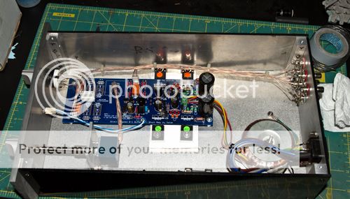
Post a close enough clear photo so we may spot what's wrong. You probably shorted them MOSFETs backs.
The two main "pass" mosFETs do not dissipate maximum power at the same time.
This makes it economic for the two to share a heatsink. see below.
But both must be electrically isolated form the Chassis.
Worst case 1.
If the output is shorted, the CCS FET passes normal current but drops the whole supply voltage. CCS is at max dissipation and the Shunt FET has zero dissipation.
Worst case 2.
When output is open circuit, the Shunt FET is at max dissipation. Now the TOTAL dissipation of both FETs is the same as the worst case in the shorted condition. The same size heatsink will have the same power input.
Nortmal case.
When operating normally the total heatsink dissipation is less than the two worst cases above and the FETs will run cooler.
my Hot Mosfets
Thanks gents,
I will post a picture when i can get my hands on my camera - strange to relate all the voltages are " ball park" and the DC offset is also OK (low- 5 mv / 1 mv) but its to hot (well one side is) , I will read posts and digest- get back soon, thanks boys.
Johnny
Thanks gents,
I will post a picture when i can get my hands on my camera - strange to relate all the voltages are " ball park" and the DC offset is also OK (low- 5 mv / 1 mv) but its to hot (well one side is) , I will read posts and digest- get back soon, thanks boys.
Johnny
and
PS The mosfets that get hot each have there own heat sink and not joined to anything else.
PS The mosfets that get hot each have there own heat sink and not joined to anything else.
The two main "pass" mosFETs do not dissipate maximum power at the same time.
This makes it economic for the two to share a heatsink. See below.
But both must be electrically isolated from the Chassis.
Worst case 1.
If the output is shorted, the CCS mosFET passes normal current, but drops the whole supply voltage. CCS is at max dissipation and the Shunt mosFET has zero dissipation.
Worst case 2.
When output is open circuit, the Shunt mosFET is at max dissipation. Now the TOTAL dissipation of both mosFETs is the same as in the worst case 1 (the shorted condition). The same size heatsink will have the same power input.
Normal case.
When operating normally the total heatsink dissipation is less than the two worst cases above and the FETs will run cooler.
repost with errors corrected.
I am about finished with making my chassis and ready to start stuffing the PCB
I only need 2 inputs so will there be a problem with using only two relays and leaving the other spots just empty. It looks like the single path tones out with my DMM with out the use of jumpers is this correct.
Thanks Dave
I only need 2 inputs so will there be a problem with using only two relays and leaving the other spots just empty. It looks like the single path tones out with my DMM with out the use of jumpers is this correct.
Thanks Dave
Pass DIY Addict
Joined 2000
Paid Member
If you only need two inputs, then only use two relays... No harm in leaving the rest empty. I have need for 2-3 inputs, so I installed only 4 relays and diodes.
I'm not exactly clear what you asking in your second question.
I'm not exactly clear what you asking in your second question.
I used three inputs and left off the relays and diodes for the other three. No jumpers are needed.
Just finished my DCB1 the hardest part was making the chassis a lot of test fitting it was my first time making a chassis all out of medal. I used Nichicon KG electrolytic caps and PRP and Vishay resistor, and Cardas RCA's. Everything tested spot on power up and it just sounds wonderful so much more depth to the sound stage I couldn't believe it I thought the B1 sounded good but this is another level.
Thanks Salas and everyone else that had a part in bring this to life. Here is a few photos.


Thanks Salas and everyone else that had a part in bring this to life. Here is a few photos.


Its only there when you connect a phono stage VS any line level source on that same input? Surely the phono stage does not produce that hum when connected to another preamp? Try making the DCB1 chassis grounded using a wire from its PSU 0 to chassis if that will help the general scheme of things with the phono.
Typically a ground problem. Check TT ground connection and connection to phono stage ground terminal, perhaps try an external ground connection from TT/phono to Mez ground. If you disconnect inputs to phono does it disappear?
Its only there when you connect a phono stage VS any line level source on that same input? Surely the phono stage does not produce that hum when connected to another preamp? Try making the DCB1 chassis grounded using a wire from its PSU 0 to chassis if that will help the general scheme of things with the phono.
The hum follows the inputs either one the phono plugged into. Are you saying add a wired to the center tap then to the chassis
Sent from my iPhone using Tapatalk - now Free
Typically a ground problem. Check TT ground connection and connection to phono stage ground terminal, perhaps try an external ground connection from TT/phono to Mez ground. If you disconnect inputs to phono does it disappear?
Yes hum goes away when I unplug the phono
Yes hum goes away when I unplug the phono
So, it's more than likely the turntable ground. Either a ground loop, or no ground. Can you ground the turntable to the phono stage? Does the hum go away - no TT ground. If you lift the TT ground does the hum go away - TT and phono ground causing ground loop.
Typically a ground problem. Check TT ground connection and connection to phono stage ground terminal, perhaps try an external ground connection from TT/phono to Mez ground. If you disconnect inputs to phono does it disappear?
Yes hum goes away when I unplug the phono
Are you saying add a wired to the center tap then to the chassis
Yes
- Home
- Amplifiers
- Pass Labs
- Mezmerize DCB1 Building Thread