Ignore that. The BC517 worked better than BC546 originally there, we had to occasionally add that cap there to avoid the startup relay from ocilllating.
So 4 100uf caps for Power supply , 1 for relay cap.
The board is labeled correctly for all needed parts.
So 4 100uf caps for Power supply , 1 for relay cap.
The board is labeled correctly for all needed parts.
Its all ready there for you. There is 12V supply on board -connected as it should, you do nothing- and there are 1...6 positions for the steps pins and gnd for the switch's output pin. Half a stereo switch does the trick.
The other half for input identification via leds... 😉
Actually it's still not clear to me as well how to connect the input selector. I have 7 pins. What do I have to connect to the common pole of the selector ?
I fired today for the first time the board. Everything looks good. I have one rail a bit lower than the other. Additionally 0.1 mV DC offset on one channel and 1.8mV on the second channel. Is it normal ?
Thanks,
Davide
I fired today for the first time the board. Everything looks good. I have one rail a bit lower than the other. Additionally 0.1 mV DC offset on one channel and 1.8mV on the second channel. Is it normal ?
Thanks,
Davide
Davide
It looks like congratulations are in order. Your offset is wonderful. I think one rail actually is supposed to be lower than the other but by how much I dont recall.
Uriah
It looks like congratulations are in order. Your offset is wonderful. I think one rail actually is supposed to be lower than the other but by how much I dont recall.
Uriah
Actually it's still not clear to me as well how to connect the input selector. I have 7 pins. What do I have to connect to the common pole of the selector ?
There is text beside the pin row, SELECTOR 1,2,3,4,5,6,GND.
So the pin closest to the text is GND and connecting it to the 1,2,3,4,5,6 pins will drive the corresponding relay.
Hopefully this helps.
Actually it's still not clear to me as well how to connect the input selector. I have 7 pins. What do I have to connect to the common pole of the selector ?
I fired today for the first time the board. Everything looks good. I have one rail a bit lower than the other. Additionally 0.1 mV DC offset on one channel and 1.8mV on the second channel. Is it normal ?
Thanks,
Davide
Attachments
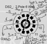
There is text beside the pin row, SELECTOR 1,2,3,4,5,6,GND.
So the pin closest to the text is GND and connecting it to the 1,2,3,4,5,6 pins will drive the corresponding relay.
Hopefully this helps.
It does. 🙂
Thanks,
D.
Horio,
Let me correct myself first, it's the first cap that gets replaced, not the second.
Technically I am not positive what the differences are. Both are bypass caps for the IRFP Voltage Reference. The film cap seems to offer better sound. I would buy both and try both.
Tea-Bag
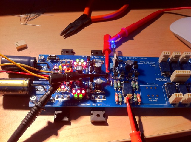
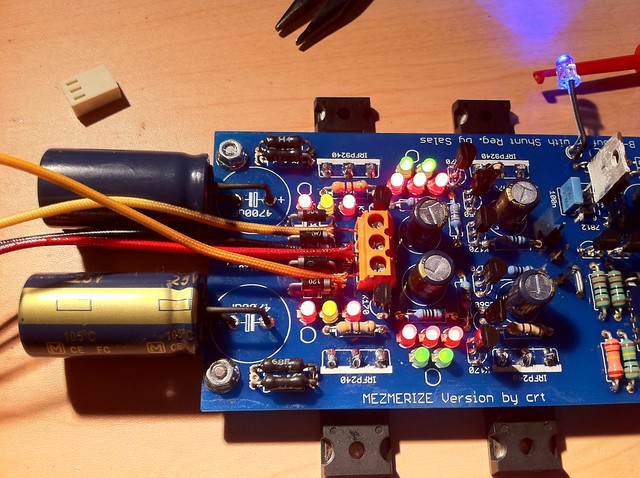
I'm getting ready to solder in the caps, and wanted to make sure I put the 0.1uF cap in the right spot. I should be replacing the two 100uF caps closest to the Vref LED strings (5 LEDs) for hot-rod?
I'm getting close to finishing populating the boards. I still need to pull two matching sets of (4) 2SK170BL's from (50) I bought from Zhoufang. I've got a couple of transformers coming from Sumr too. Getting closer...
Horio,
there are only two pair (as in the B1) that need selecting for Idss. Idss within 1% is probably close enough, but the two pairs do not need to be exactly equal to each other.
The other jFets do not need precise selection.
there are only two pair (as in the B1) that need selecting for Idss. Idss within 1% is probably close enough, but the two pairs do not need to be exactly equal to each other.
The other jFets do not need precise selection.
Andrew,
Thanks for the advice. It should be easier only having to pull matched pairs that are close instead of a matched quad. I'm doing a balanced build (2 boards), so that's why mentioned two matched sets.
Thanks for the advice. It should be easier only having to pull matched pairs that are close instead of a matched quad. I'm doing a balanced build (2 boards), so that's why mentioned two matched sets.
Dear All,
I have finished the circuit of my DCB1, just waiting to put it in a box, did not have any chance to use it.
Anyway, as I plan to use it as a pre for a F5, I was thinking of installing a relay on the power switch of the power amp, and derive 12 V from the relay of the delay start. If I got it right, like this I will power on the DCB1 and when the relay will open the power amp will switch on.
Does it make sense ? Is it as easy as I think ? The relay on the F5 will be 12 V as the one on the DCB1.
Thanks,
Davide
I would prefer you will not drive a further (likely heavier) relay for an F5, because its power consumption and inductance can be overwhelming for the dedicated circuit, which is calculated to control 2 mini relays the most in the Mez's case.
New born.
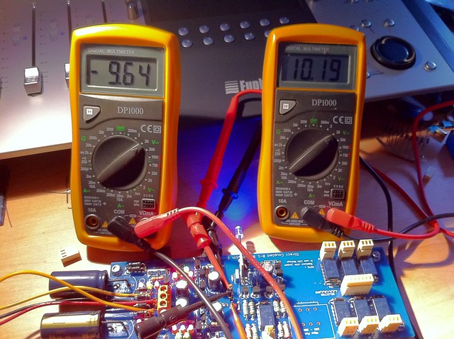
V.out
10.18V pos
-9,66V Neg
Ofset:
R= -1.2 mV
L= 0.5 mV
Tomorrow I'll get a pot and I'll hear it.
Thanks Salas! (And all the other involved).
V.out
10.18V pos
-9,66V Neg
Ofset:
R= -1.2 mV
L= 0.5 mV
Tomorrow I'll get a pot and I'll hear it.
Thanks Salas! (And all the other involved).
Last edited:
Mes boards arrive
Many thanks to Tea-Bag, my Mesmerize boards arrived today in Australia!
I also, yesterday, just go home from hospital after surgery to reassemble my left wrist - snapped it into a thousand pieces falling over very clumsily... So I won't be building the boards for a few weeks yet.
I know this url http://www.diyaudio.com/forums/blogs/tea-bag/173-old-style-dcb1-information.html , but is there a complete circuit of the Mez somewhere with part designations which relate to the PCB?
I am using them on a balanced LDR volume control and I already have input selection so I am only building the buffers and shunt regulators - need to get that bit right.
Great xmas or whatever you do to all, and happy new year, thanks again Tea-Bag,
- Home
- Amplifiers
- Pass Labs
- Mezmerize DCB1 Building Thread